Address
304 North Cardinal St.
Dorchester Center, MA 02124
Work Hours
Monday to Friday: 7AM - 7PM
Weekend: 10AM - 5PM
Address
304 North Cardinal St.
Dorchester Center, MA 02124
Work Hours
Monday to Friday: 7AM - 7PM
Weekend: 10AM - 5PM
Get premium quality cable management systems directly from the manufacturer.
Fill out the form below to receive our catalog and pricing.
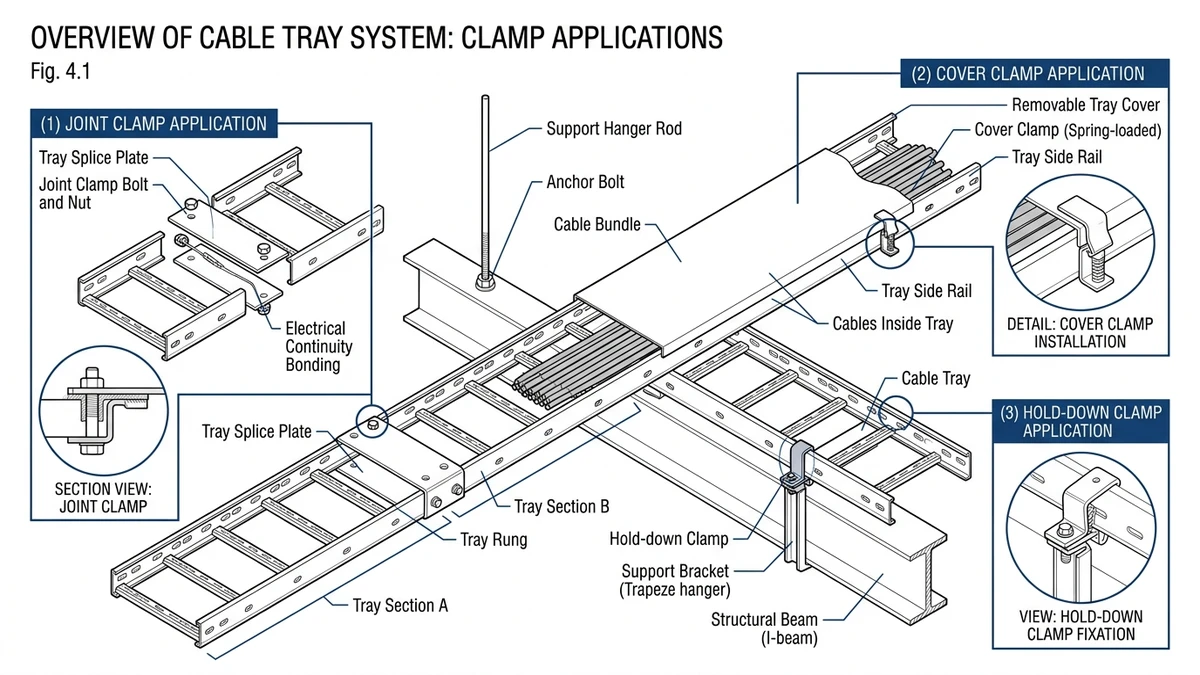
Cable tray clamps are mechanical fasteners used to secure a cable tray, cable ladder, cover, splice plate, or cable bundle to the supporting structure. In real installations, they transfer dead load, vibration, uplift, thermal movement, and sometimes fault-related forces through relatively thin steel or aluminum members. If the tray is load-rated but the clamp does not match the actual load path, the assembly can lose alignment, bonding continuity, or support reliability before the tray rail itself fails.
Cable tray clamps make separate tray parts behave like one assembly. They align sections, transfer load through joints and supports, restrain movement, and in some cases help maintain electrical continuity across metallic tray runs.
A tray span rated for 2 m to 3 m under 50 kg/m to 200 kg/m only performs that way if the clamp set and joint hardware can carry the same shear, bearing, and slip forces. Otherwise, the weak point shifts from the tray rail to the connection.
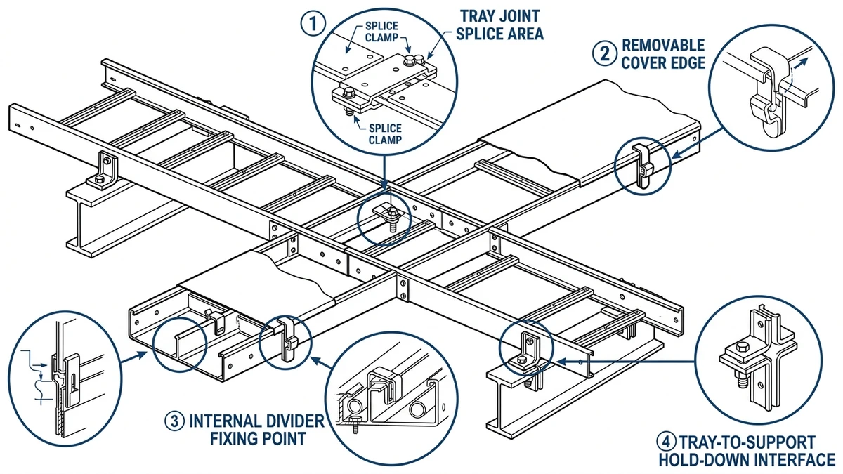
In straight runs, clamps keep tray sections in line so joint errors do not build up into cover fit problems, support eccentricity, or poor cable routing. At supports and fittings, they also transfer load across discontinuities, which is especially important at risers, reducers, elbows, and branches.
IEC 61537 evaluates the cable tray system as an assembly, not just as isolated tray lengths, so the connection detail matters as much as the section rating. See the IEC publication page here.
Some cable tray clamps also contribute to electrical continuity for protective bonding. A clamp can be mechanically secure but electrically poor if paint, powder coating, or insulating washers interrupt metal-to-metal contact.
Where the tray is expected to assist the fault path, low-impedance continuity affects relay operation and touch-voltage control. That makes clamp selection an electrical check as well as a mechanical one.
During cable pulling, local side loads at bends and drop-outs can be much higher than normal dead load. In practice, clamp movement usually appears first at these locations rather than at mid-span straight sections.
Typical signs are slip, cover misalignment, and witness marks from under-torqued or poorly seated hardware. For related system context, Xinma’s overview of cable management system applications is useful when mapping clamp function to route type.
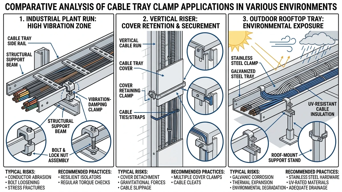
Cable tray clamps matter most where the system sees movement, uplift, vibration, or concentrated force rather than only static cable weight. In these conditions, the clamp detail often becomes the governing reliability point.
Outdoor tray routes add wind uplift, thermal cycling, moisture, and corrosion. Over a 20 m run, seasonal temperature swings can produce measurable expansion or contraction that concentrates at splices, hold-down points, and support brackets.
The main design point is not to restrain every support as if the tray must be fixed everywhere. In long exposed runs, one anchor point plus guided sliding supports is often safer than repeated full restraint.
Risers shift the load case from mainly transverse loading to sustained axial load from cable weight and hold-down points. Heavy power cables can impose 50 kg/m to 150 kg/m, and that force transfers into side rails, brackets, and clamp interfaces.
If clamp spacing is too large or hardware is not rated for axial loading, the common failure mode is local slip or side-member distortion rather than obvious fracture. This is where generic hardware often fits physically but fails to hold geometry in service.
Near generators, HVAC plant, rail infrastructure, or process equipment, clamps must resist cyclic loosening. Repeated small movement can enlarge holes, reduce clamping force, and degrade continuity between metallic tray sections.
Use locking features, serrated bearing faces, or anti-vibration arrangements where dynamic input is persistent, especially on support spans of 1.5 m to 3.0 m.
[Expert Insight]
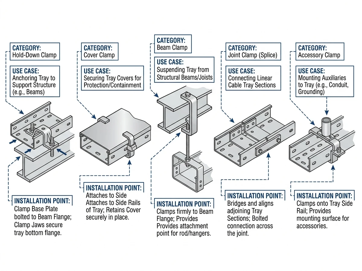
Cable tray clamps include beam clamps, U-bolts, hold-down clamps, splice clamps, cable cleats, and cover clamps. The right choice depends on load path, restraint function, environmental exposure, and whether the clamp affects structural continuity, short-circuit restraint, or access time.
| Clamp type | Main mechanism | Typical rating check | Best use case | Main trade-off |
|---|---|---|---|---|
| Beam clamp | Grips structural steel flange to support rod or bracket | Working load in kN, flange thickness, uplift behavior | Fast attachment to steel where drilling is restricted | Capacity depends heavily on flange geometry and orientation |
| U-bolt clamp | Wraps around round or tubular support to create radial restraint | Diameter fit, crush risk, corrosion finish | Pipe racks, round supports, moderate vibration | Over-tightening can deform lighter tray members |
| Hold-down clamp | Locks tray to support against uplift or lateral shift | Clamp spacing, restraint direction, thermal movement strategy | Rooftops, exposed corridors, seismic or wind-prone areas | Too many fixed points can block thermal expansion |
| Splice clamp or coupler | Transfers longitudinal load and aligns adjacent sections | Bolt size, slip resistance, joint strength, continuity | Field-assembled tray runs where joint performance governs span reliability | Joint capacity may be lower than the parent tray section |
| Cable cleat or cable clamp | Restrains individual cables under electromechanical fault force | Cable diameter, spacing, short-circuit withstand in kA | Single-core power cables, vertical runs, high-fault-duty circuits | Adds spacing checks and installation time |
| Cover clamp | Retains tray cover against weather, vibration, or tampering | Retention spacing, reopening frequency | Outdoor or dusty environments | Slows inspection and cable additions |
A splice clamp is a structural continuity component, a cable cleat is an electromechanical restraint device, and a cover clamp mainly affects enclosure security and maintenance speed. Treating them as interchangeable hardware leads to poor specifications.
A common mistake is using hold-down clamps at every support on a long aluminum tray run. That may improve uplift resistance but can also lock thermal movement into too many points and increase force at splices and brackets.
Use when structural steel is available and drilling or hot work is restricted. Check flange geometry, orientation, and actual support load before specifying.
Use on round supports where the tray member can tolerate local bearing pressure. Avoid them on light-gauge members if over-tightening could crush the section.
Use where positive restraint against uplift, lateral movement, or seismic displacement is required. Check which supports are fixed points and which must allow sliding.
Use where joint alignment and continuity control installed performance. Avoid generic replacements if the tray’s tested rating depends on a specific splice detail.
Use when short-circuit forces, cable whip, or trefoil spacing govern design. Check fault level and cleat spacing, not just cable diameter.
Use where wind, dust, or vibration could dislodge the cover. Avoid them where frequent inspection or cable additions make repeated cover removal likely.
For tray geometry and width coordination, this guide to tray dimension planning helps connect clamp choice to the overall support layout.
[Expert Insight]
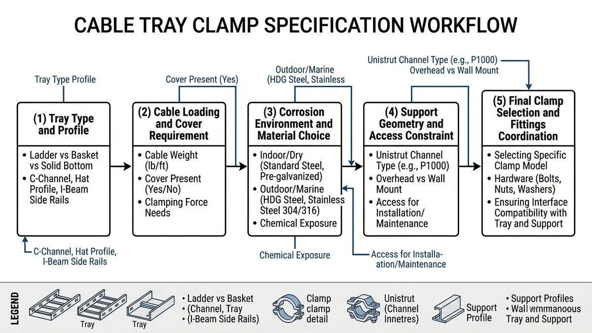
Before specifying cable tray clamps, verify fit, force direction, environmental compatibility, electrical duty, and installation access. A good specification states not only the clamp type, but the service condition it must survive.
Start with side rail thickness, flange shape, engagement length, and tray type. If the clamp does not seat correctly on the real rail profile, contact area drops, local stress rises, and the published load rating may no longer represent the installed connection.
This matters especially with side members in the 1.5 mm to 3.0 mm range and when coordinating with ladder tray configurations, where rail and rung geometry can affect hardware engagement.
Do not size clamps only from distributed dead load. The governing force may come from uplift, thermal restraint, seismic action, cable pulling tension, or a concentrated load at a fitting.
A clamp acceptable for downward loading may still be unsuitable for cyclic lateral or shock loading. On some routes with only 20 kg/m to 50 kg/m cable load, a clamp may still need to resist 1.5 kN or more in a specific direction.
Match clamp material to tray material and service environment. Zinc-plated steel may suit dry indoor areas, while coastal, washdown, or chemical environments usually require hot-dip galvanized steel or stainless steel such as SS304 or SS316.
Corrosion often starts at threads, cut edges, and bearing surfaces before the tray body shows major damage. Mixed metals can also accelerate galvanic attack where moisture is present.
If the clamp contributes to bonding, check continuity performance as part of the installed metallic path. Coatings, painted rails, or nonconductive washers can interrupt that path even when the mechanical connection feels tight.
Mechanical retention does not guarantee acceptable electrical contact, so confirm whether separate bonding jumpers are required.
A clamp that is hard to open or torque correctly becomes a maintenance problem on routes with frequent inspection, cable additions, or periodic cleaning. Awkward access often leads to inconsistent tightening and field modification.
For support spacing and bracket coordination, Xinma’s article on support arrangement for tray runs is a useful companion during specification review.
Clamp selection changes four design checks at once: loading, access, corrosion life, and support coordination. That is why cable tray clamps should be specified as system components, not as generic fasteners added after tray width and span are fixed.
A clamp may weigh only 0.2 kg to 0.6 kg per fixing point, but across a 30 m route with supports at 1.5 m to 3.0 m spacing, the added hardware and restraint points can still affect bracket loading and local tray behavior. Near the upper end of the tray load class, clamp arrangement often changes joint behavior and deflection more than straight-section weight alone.
Some clamp designs require full removal for each inspection or cable addition, while others allow controlled reopening without damaging tray flanges or losing alignment. On retrofit-heavy routes, that difference affects labor hours more than the initial hardware price.
Maintenance teams usually prefer repeatable hardware that can be reopened without damaging galvanized or stainless surfaces, because damaged bearing faces reduce future clamping reliability.
The tray, clamp, support steel, and coating system should be reviewed together. A stainless clamp on a galvanized tray may improve fastener life but can also create mixed-metal exposure at wet interfaces if the detail is not isolated correctly.
The right choice depends on actual exposure, cleaning regime, and whether moisture stays trapped at the contact point.
If the project includes bends, tees, risers, hold-down points, and support steel from different vendors, a technical review before release can prevent site mismatch. The most useful checks are joint rating, support interface, fixed-versus-sliding support locations, corrosion compatibility, and continuity requirements.
For projects that need coordinated tray, fittings, supports, and restraints, Xinma’s cable tray system range and seismic bracing solutions are best reviewed together at specification stage so the final assembly is checked as a system rather than as unrelated parts.
Check whether it transfers tray load, restrains movement, or only retains a cover or cable. If it affects joint strength, uplift resistance, or support behavior, it should be treated as a structural component in the specification.
Sometimes, but the detail should be reviewed for galvanic exposure, trapped moisture, and coating damage at contact points. Mixed-metal combinations may be acceptable indoors yet problematic in wet or coastal service.
Inspection frequency usually depends on environment and route criticality. Outdoor, vibrating, or high-maintenance runs often justify closer review than stable indoor service areas.
They can be, especially on metallic tray systems where continuity across joints matters to the protective path. Mechanical tightness alone does not confirm acceptable electrical contact.
A common issue is selecting by appearance or nominal fit without checking the actual force direction and support condition. That tends to cause problems at risers, outdoor fixed points, and joints near fittings.
Not necessarily. Many outdoor runs need a mix of fixed and sliding supports so the tray can resist uplift while still accommodating thermal movement.
It may fit physically, but it does not necessarily match the tested joint strength, slip resistance, or continuity performance of the original system. Replacement hardware should be checked against the tray assembly requirements, not only bolt size.
