Address
304 North Cardinal St.
Dorchester Center, MA 02124
Work Hours
Monday to Friday: 7AM - 7PM
Weekend: 10AM - 5PM
Address
304 North Cardinal St.
Dorchester Center, MA 02124
Work Hours
Monday to Friday: 7AM - 7PM
Weekend: 10AM - 5PM
Get premium quality cable management systems directly from the manufacturer.
Fill out the form below to receive our catalog and pricing.
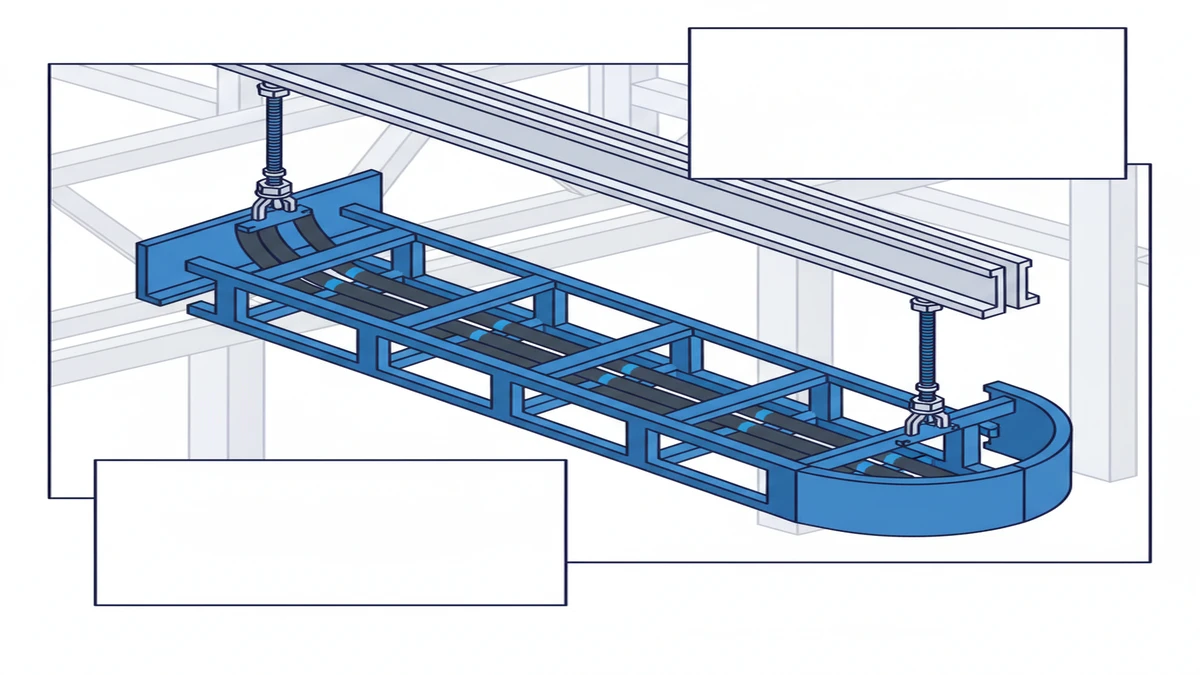
A cable ladder is an open-framework cable management system used to support and route electrical cables across industrial, commercial, and infrastructure environments. Built from two parallel side rails joined by transverse rungs — exactly as the name suggests — it carries heavy cable loads over long unsupported spans without the volume penalty of conduit banks or the thermal restriction of enclosed trays.
Defined under IEC 61537 (Cable management — cable tray systems and cable ladder systems), the cable ladder is a distinct product category from solid-bottom trays, specifically engineered for high fill density and thermal performance. Load classes range from 50 kg/m (Class A) through 200 kg/m (Class D), giving engineers a structured selection framework rather than a rule-of-thumb.
A cable ladder is the heavy-duty anchor of the cable management family. Two longitudinal side rails, spanned at regular intervals by transverse rungs, create a rigid open-frame assembly that supports power, control, and instrumentation cables across spans of 1.5 m to 6 m between support brackets. The open base is not a simplification — it is the defining technical advantage, allowing natural convective airflow to dissipate heat from cable surfaces and preserve ampacity without forcing conductor oversizing.
Within IEC 61537, cable ladders are distinguished from cable trays by this rung construction and by their load class ratings. The standard sets maximum midspan deflection at span ÷ 200 (15 mm for a 3 m span under Class C loading), giving installers a concrete acceptance criterion rather than a visual judgment call.
A standard cable ladder unit spans 3 m between support brackets. Rung spacing runs from 150 mm to 300 mm, determined by the minimum bend radius of the cables being carried — tighter spacing for smaller, denser cables prone to sagging; wider spacing for stiff, large-diameter power cables with enough body to bridge the gap cleanly.
Side rail height is selected from standard depths of 60 mm, 100 mm, and 150 mm based on cable fill depth and structural load. Rails are typically hot-dip galvanized steel or aluminum alloy; rungs are welded or press-fitted to the rails, and weld quality is a direct input to the ladder’s rated load class under IEC 61537. The splice plates and fish plates joining consecutive sections also carry a secondary function: maintaining electrical continuity across the full run for earthing and bonding purposes.
Cable ladders occupy the heavy-duty end of the routing spectrum. Wire mesh trays handle lightweight data and signal cables where flexibility matters more than load capacity. Solid-bottom trays offer mechanical drip protection for medium-density instrument cables. Enclosed conduit and ducting provide maximum mechanical protection for individual circuits at the cost of fill flexibility.
Cable ladders are specified when the installation involves power cables with cross-sections of 35 mm² or larger, high fill densities, or spans exceeding 2 m between supports. In a 2023 petrochemical plant expansion in Guangdong Province — 24 cable routes, 1,800 m total run length — the project team selected hot-dip galvanized ladders rated at 150 kg/m to carry 630 mm² HV feeder cables across 3 m unsupported spans. Achieving equivalent fill capacity with conduit would have required banks roughly three times the installed volume. For a complete overview of how cable ladders integrate with fittings and support hardware, the cable tray systems page covers the full system architecture from straight sections through to accessories.
[Expert Insight]
– IEC 61537 Table 1 sets four load classes (A–D) with corresponding maximum deflection limits; specifying the class in the procurement document — not just the kg/m figure — prevents substitution with under-rated systems that meet weight capacity but fail deflection criteria.
– Rung spacing has a direct relationship to cable jacket wear: where vibration is present (pump rooms, compressor decks), 150 mm spacing reduces point-contact fatigue on cable sheaths over a 20-year service life.
– Hot-dip galvanized steel and aluminum each have a place; aluminum is preferred above 400 m elevation in coastal zones where zinc corrosion rates accelerate, but requires isolation from steel structure to prevent galvanic corrosion at contact points.
– Always verify the load class test report references IEC 61537 Annex C test conditions — manufacturer claims based on proprietary test rigs are not directly comparable.
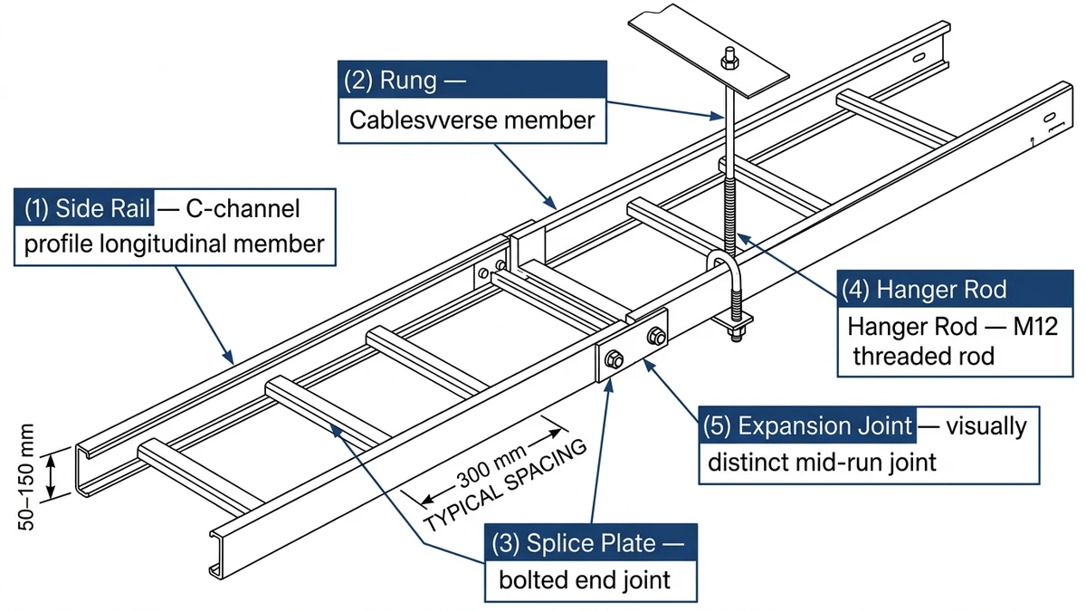
The physical geometry of a cable ladder is straightforward. What determines whether a system performs to specification in service is the dimensional coordination between components — rail depth, rung spacing, span length, and support bracket type — and the material grade selected for the operating environment.
Side rails are the longitudinal load-bearing spine. Standard channel depths are 60 mm, 100 mm, and 150 mm. Depth governs how much vertical cable fill the ladder can accommodate before bundles overflow the rail profile or approach the fill ratio limit. Rail sections are supplied most commonly in 3 m or 6 m lengths to align with standard support spacing, reducing the number of splice joints per run.
Rungs bear the direct weight of cables laid across them. Standard center-to-center spacing is 300 mm or 600 mm: 300 mm for smaller, denser cables that would sag and stress between supports; 600 mm for large stiff cables with enough structural body to span the gap without deflection. Weld quality at the rung-to-rail joint is the primary mechanical determinant of the ladder’s rated load class under IEC 61537 — a poorly executed weld reduces the effective load capacity regardless of the steel grade specified.
A complete installation requires horizontal bends (30°, 45°, 90°), tee pieces, reducers, and riser sections. These fittings allow routing paths to change direction without imposing tight bend radii on the cables themselves — a common source of insulation damage when improvised bends or cable ties are used to force direction changes on rigid power cables. Splice plates join ladder sections end-to-end while maintaining earthing continuity across the system.
In a 2023 petrochemical plant expansion in Shandong Province covering approximately 4,200 linear meters of cable routing, engineers selected 100 mm deep, 600 mm wide steel cable ladders on 3 m support spans. Under the project’s design load of 90 kg/m, midspan deflection measured 11 mm — within the IEC 61537 Class C maximum of span ÷ 200, or 15 mm for a 3 m span. The result confirmed that component geometry and material grade together govern in-service performance; neither factor alone is sufficient.
[Expert Insight]
– Midspan deflection under working load is the practical failure mode most often missed in procurement; request the manufacturer’s load-deflection test curve (IEC 61537 Annex C), not only the rated kg/m figure.
– 6 m rail sections reduce splice joints by half compared to 3 m sections on long runs — fewer joints means fewer potential earthing discontinuities and lower site labour cost per metre installed.
– In corrosive process areas (pH < 5 or salt-laden atmospheres), glass-fibre reinforced polymer (GRP) ladder systems are a viable alternative; verify flame spread index to IEC 61537 and local fire code before specifying.
Cable ladders occupy a specific position within the broader cable management family. Understanding where they fit — and where they do not — prevents specification errors that generate rework.
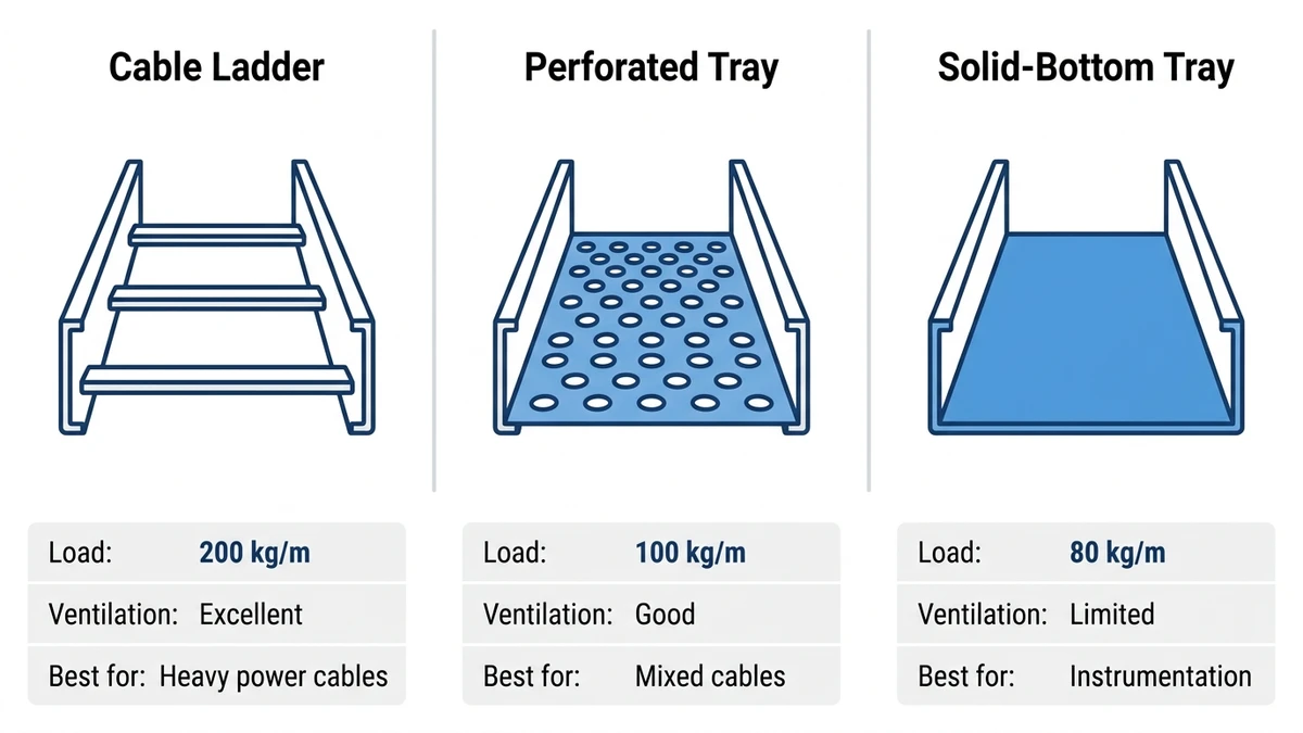
Cable management systems divide into three primary categories based on construction and application:
No single system suits all routes on a project. The engineering judgment lies in matching system type to the cable population on each run.
The rung-and-rail geometry delivers two structural advantages that tray alternatives cannot replicate at the same scale.
Airflow. Because the ladder base is open, heat dissipates freely from cable surfaces by natural convection. IEC 61537 recognizes this by permitting higher ampacity retention in open ladder systems compared to solid-bottom trays — relevant when routing 185 mm² or 240 mm² power cables in process plants, where derating losses translate directly into conductor oversizing and increased material cost.
Load capacity. Ladder systems routinely achieve IEC 61537 Class D ratings (200 kg/m) spanning up to 6 m between supports with correctly sized steel or aluminum rails. Perforated trays at equivalent span widths typically reach 75–100 kg/m before deflection limits are exceeded.
In a 2023 petrochemical plant expansion in Zhoushan, China, the engineering team replaced solid-bottom trays with ladder systems on six cable riser runs carrying 66 kV medium-voltage feeder cables. The change reduced forced ampacity derating by 12% and eliminated two planned cable upsizing steps, saving approximately CNY 380,000 in conductor material. Projects requiring both ladder and perforated sections can reference the perforated cable tray specifications to plan split routing layouts by cable class.
Cable ladders are not the universal answer:
Matching the system type to the cable population on each route — rather than defaulting to one product across all runs — is the defining competency in cable routing design.
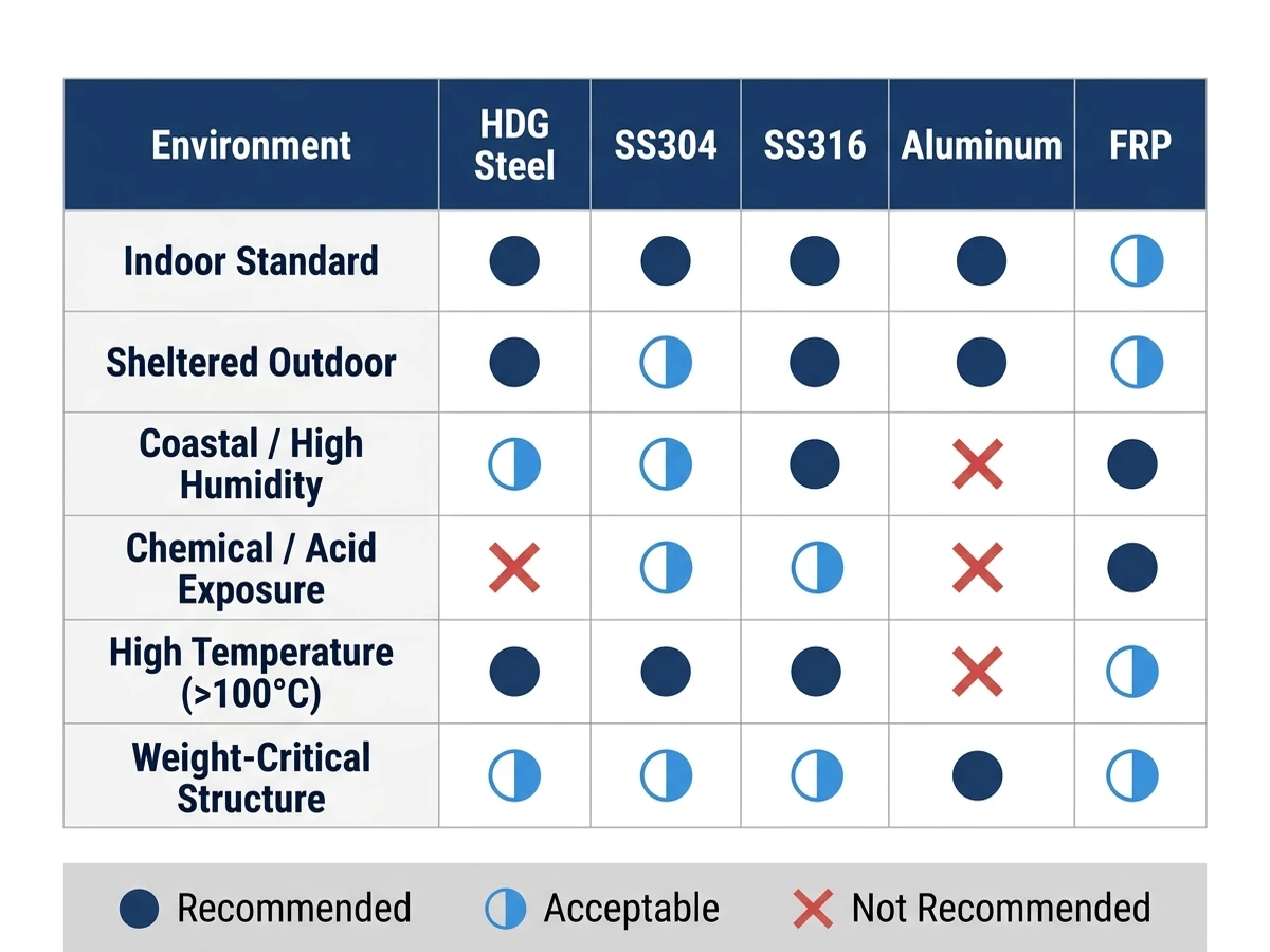
The long-term performance of a cable ladder system is as much a materials decision as a structural one. Choosing the wrong finish for an operating environment is a frequent source of premature replacement — a cost that far exceeds the initial material premium for specifying correctly.
Hot-dip galvanized (HDG) steel is the standard specification for indoor industrial environments and sheltered outdoor installations. The zinc coating applied during hot-dip galvanizing — typically 45–85 µm for structural sections to ISO 1461 — provides barrier and sacrificial protection, with service lives of 20–40 years in moderate industrial atmospheres.
HDG is cost-effective where the environment is not aggressively corrosive. It is not suitable for continuous contact with acidic process liquids, chloride-rich marine atmospheres without additional protection, or food-grade facilities where zinc leaching is a contamination concern.
Grade 316L stainless steel is specified for offshore platforms, coastal chemical plants, and food-processing facilities. The molybdenum content in 316L provides resistance to chloride-induced pitting that standard 304 stainless cannot match. The cost premium over HDG steel is significant — typically 3–5× by material weight — so stainless steel cable ladders are confined to routes where the corrosion case is clear.
Aluminum cable ladders offer a weight advantage of roughly 65% compared to equivalent-rated steel sections, making them practical for elevated cable bridges and offshore topsides where structural dead load is constrained. The naturally forming aluminum oxide layer provides reasonable atmospheric corrosion resistance, but direct contact with carbon steel structure must be avoided to prevent galvanic corrosion; neoprene or PTFE isolation pads are standard practice at support points.
GRP cable ladders are the specification choice for chemically aggressive environments — sulfuric acid service areas, offshore splash zones, and water treatment facilities — where metallic options require frequent maintenance. GRP is non-conductive, which eliminates earthing continuity across ladder sections as a passive safety feature; however, this requires separate earthing conductors for any cables that depend on the ladder for fault-current return paths. Flame spread index must be verified against IEC 61537 and applicable local fire codes before specifying GRP in enclosed plant areas.
Selecting a cable ladder system requires coordinating four interdependent variables: span, load, width, and rail depth. Changing one affects the others, and the interaction is governed by IEC 61537 test-class requirements rather than by simple rule of thumb.
The span between support brackets determines the bending moment the rails must carry. IEC 61537 Class C is the most common industrial specification — load up to 150 kg/m, maximum deflection span ÷ 200. For a 3 m span, that is a 15 mm deflection limit; for a 6 m span, the limit increases to 30 mm in absolute terms but the required rail section depth increases substantially to meet it.
When cable fill density is uncertain at design stage, specifying Class D (200 kg/m) adds headroom for future cable additions without re-engineering the support structure — a useful buffer on projects where instrument loop additions typically accumulate during commissioning.
Standard widths are 150 mm, 200 mm, 300 mm, 400 mm, 450 mm, 600 mm, and 900 mm. Width selection follows from the cable fill calculation: the sum of cable cross-sectional areas should not exceed 40% of the available tray cross-sectional area for power cables, in line with general good practice and the cable manufacturer’s ampacity derating tables. A 600 mm wide, 100 mm deep ladder has a nominal fill area of 60,000 mm²; the usable fill zone at 40% is 24,000 mm².
Rail depth (60 mm, 100 mm, 150 mm) governs both the vertical fill capacity and the structural stiffness of the assembly. Deeper rails carry more cables per unit width and deflect less under equivalent load — but add cost and weight. The 100 mm depth is the most common general industrial specification, balancing capacity, cost, and availability across most project types.
Support brackets must be rated to carry the concentrated reaction load at each span. For a 150 kg/m loaded ladder on a 3 m span, each bracket must carry at least 450 kg (4.4 kN) under full load — this is the minimum bracket rating, before safety factors required by the structural engineer. Cantilever brackets introduce an additional bending moment at the wall or steelwork fixing point; the structural team must verify the fixing capacity independently of the ladder manufacturer’s bracket rating.
Correct installation practice determines whether a cable ladder system achieves its rated service life and maintains electrical safety throughout.
A cable ladder used as the protective earthing conductor for cable systems must maintain electrical continuity across every splice joint. Splice plates and fish plates provide this continuity when correctly torqued to the manufacturer’s specification — typically 12–20 N·m for M8 stainless fasteners, depending on rail material. Painted or heavily corroded contact surfaces at splice points increase joint resistance and compromise the earthing path; abrading the contact zone to bare metal before assembly is standard practice on quality-conscious projects.
Where the ladder system is not used as the primary earth conductor, a separate earthing conductor bonded to the ladder at regular intervals — typically every 15–20 m — maintains the structure at earth potential and prevents touch-voltage hazards in fault conditions.
Cables on cable ladders should be secured at intervals consistent with the cable manufacturer’s recommendations and the IEC 61537 rung spacing. On inclined or vertical runs, cable cleats — selected in line with IEC 61914 — provide the clamping force required to resist gravitational load and short-circuit electromagnetic forces. On horizontal runs, cable ties at every second or third rung are generally sufficient for light-to-medium power cables; heavy single-core cables in trefoil arrangement require dedicated cleats to maintain formation geometry under fault current. Full ranges of compatible installation hardware are available through the cable tray accessories category, covering couplers, brackets, and bonding jumpers for system earthing continuity. The IEC webstore provides the normative IEC 61537 document governing all load class definitions and test procedures referenced in this guide.
On a 220 kV substation cable bridge inspected by this project team in Hebei Province (2022), routine 18-month visual inspections identified progressive zinc layer degradation at condensation-prone low points of the cable ladder runs — areas where moisture pooled rather than drained. Recoating with cold-applied zinc-rich epoxy at those locations extended the projected service life by an estimated 8–10 years without requiring ladder replacement. For installations in seismically active zones, supplemental seismic bracing hardware anchored to cable ladder side rails provides lateral restraint during ground motion events per GB 50981 or ASCE 7-22 requirements. The lesson is practical: inspection intervals and drainage design are as important as initial material specification.
For installations in marine or chemical atmospheres, annual visual inspection is a minimum; coating thickness measurement with a magnetic gauge at representative points adds quantitative data to the assessment. Any section showing base metal exposure should be treated before the next inspection cycle — not deferred.
For normative load-test and classification requirements, refer to IEC 61537:2023 publication details.
Related engineering references: industrial and commercial cable tray applications; dimension checks before procurement.
IEC 61537 classifies cable ladders as open-frame cable management systems with two side rails connected by transverse rungs, distinguishing them from cable trays, which use a continuous perforated or solid base. The rung-based construction is what enables higher load classes and the thermal airflow advantage that solid-bottom trays cannot provide.
Load class selection combines the calculated cable fill weight per metre with the intended support span, then references IEC 61537 Class A through D ratings to identify the minimum compliant class. Adding one class above the calculated minimum is common engineering practice on industrial projects to allow for future cable additions without structural rework.
For large, stiff power cables — typically 95 mm² and above — 600 mm rung spacing is generally appropriate because the cable body bridges the gap without sagging. Smaller or softer cables benefit from 300 mm spacing to prevent localised jacket deformation and stress concentration at the support points over a long service life.
A cable ladder can form part of the protective earthing system provided splice plates are correctly torqued, contact surfaces are free from paint or corrosion at the joint, and the system impedance has been verified to meet the earth fault loop requirements of the applicable electrical installation standard. A separate parallel earthing conductor is often installed as a redundant path on critical power distribution routes.
GRP is most appropriate in chemically aggressive environments — areas with acid vapours, persistent chloride exposure, or frequent chemical wash-down — where metallic coatings would require replacement within a few years. The trade-off is that GRP is non-conductive, so separate earthing conductors are required on every run, adding installation cost and complexity.
A 40% fill ratio — calculated as the sum of cable cross-sectional areas divided by the usable tray cross-sectional area — is widely applied for power cable installations as it preserves adequate airflow between cables and leaves margin for future additions. Exceeding this threshold can reduce natural convective cooling and push cable surface temperatures toward the jacket’s rated limit.
In standard sheltered industrial environments, an 18-month to 2-year visual inspection cycle is a reasonable baseline, with coating thickness measurement added for any sections exposed to moisture accumulation or chemical splash. Marine and offshore installations typically require annual inspection, with immediate treatment of any area where base metal is exposed to prevent accelerated corrosion from propagating to structurally significant sections.
| Decision Point | What to Verify | Recommended Evidence |
|---|---|---|
| Load and support span | Confirm the tray width, support spacing, and allowable deflection for the installed route. | Load table, drawing revision, and IEC 61537 or equivalent test reference. |
| Material and finish | Match galvanized steel, stainless steel, aluminum, or FRP to the actual corrosion and installation environment. | Material certificate, coating record, and project corrosion category. |
| Accessories and continuity | Check bends, tees, reducers, covers, couplers, clamps, grounding jumpers, and brackets. | Accessory list, bill of materials, and installation drawings. |
| Installation and code fit | Confirm grounding, bonding, cable fill, separation, and access requirements. | NFPA 70 / NEC, consultant drawings, and local electrical code. |
Use this article as the focused specification reference for its topic, then cross-check product selection against Cable Tray Systems, Ladder Cable Tray Systems, and Perforated Cable Tray Systems. This prevents overlap between general education pages and product-specific procurement pages.
