Heavy-duty ladder cable tray is an open-frame cable management system built from two parallel side rails connected by evenly spaced transverse rungs — structurally resembling a ladder laid flat. Engineered for main power cable runs, it sustains uniformly distributed loads of 150–200 kg/m under IEC 61537 Class C or Class D, making it the preferred solution where large-diameter power cables must be routed safely across long horizontal or vertical spans in industrial facilities, substations, and infrastructure projects.
The ladder configuration — rather than a solid-bottom tray or enclosed conduit — is the defining structural choice for power distribution. Its open rung design allows natural convective airflow along the full cable length, directly supporting ampacity ratings by preventing heat accumulation between conductors. This thermal management function is as critical as mechanical load capacity when routing 11 kV or 33 kV medium-voltage feeders.
Physical Construction
A heavy-duty ladder cable tray section consists of three primary components:
Side rails — formed from hot-dip galvanized steel or stainless steel, with rail heights typically ranging from 100 mm to 150 mm on heavy-duty variants; rail thickness is commonly 2.5 mm to 3.0 mm, providing the section modulus that resists bending under distributed load
Rungs — welded transversely at 250 mm to 300 mm centers, supporting individual cables, preventing sag between support points, and acting as a mechanical stop against lateral movement during seismic events or cable-pulling operations
Splice plates and couplers — connecting tray sections end-to-end while maintaining structural continuity across spans
Tray widths for heavy-duty applications commonly range from 300 mm to 900 mm. Standard section lengths are 3 m. Hot-dip galvanized steel suits most outdoor and industrial environments; stainless steel Grade 316L is specified where chloride exposure is severe.
Why “Heavy-Duty” Is a Distinct Category
Not all ladder cable tray is heavy-duty. IEC 61537 — published by the International Electrotechnical Commission and the governing international standard for cable tray and cable ladder systems — classifies load capacity in four steps, from Class A at 50 kg/m through Class D at 200 kg/m. Heavy-duty ladder tray occupies the Class C–D range.
The open-rung construction distinguishes ladder tray from solid-bottom or perforated tray in one critical respect: cables rest directly on the rungs with air circulation on all sides. This is essential for ampacity derating compliance under IEC 60364-5-52, the standard addressing thermal derating of cables in cable management systems. Every 10 °C rise above rated conductor temperature can reduce polymer insulation service life by approximately 50% — a consequence of the Arrhenius aging model for insulation degradation. Ladder tray’s open frame directly counters this mechanism.
In a 2023 petrochemical plant expansion in Shandong Province covering 4.2 km of main power cable routing, thermal imaging confirmed that heavy-duty ladder tray kept cable surface temperatures 12 °C lower than comparable enclosed duct installations under equivalent load conditions — directly supporting the ampacity ratings calculated under IEC 60364-5-52 for the 6 kV feeder cables involved.
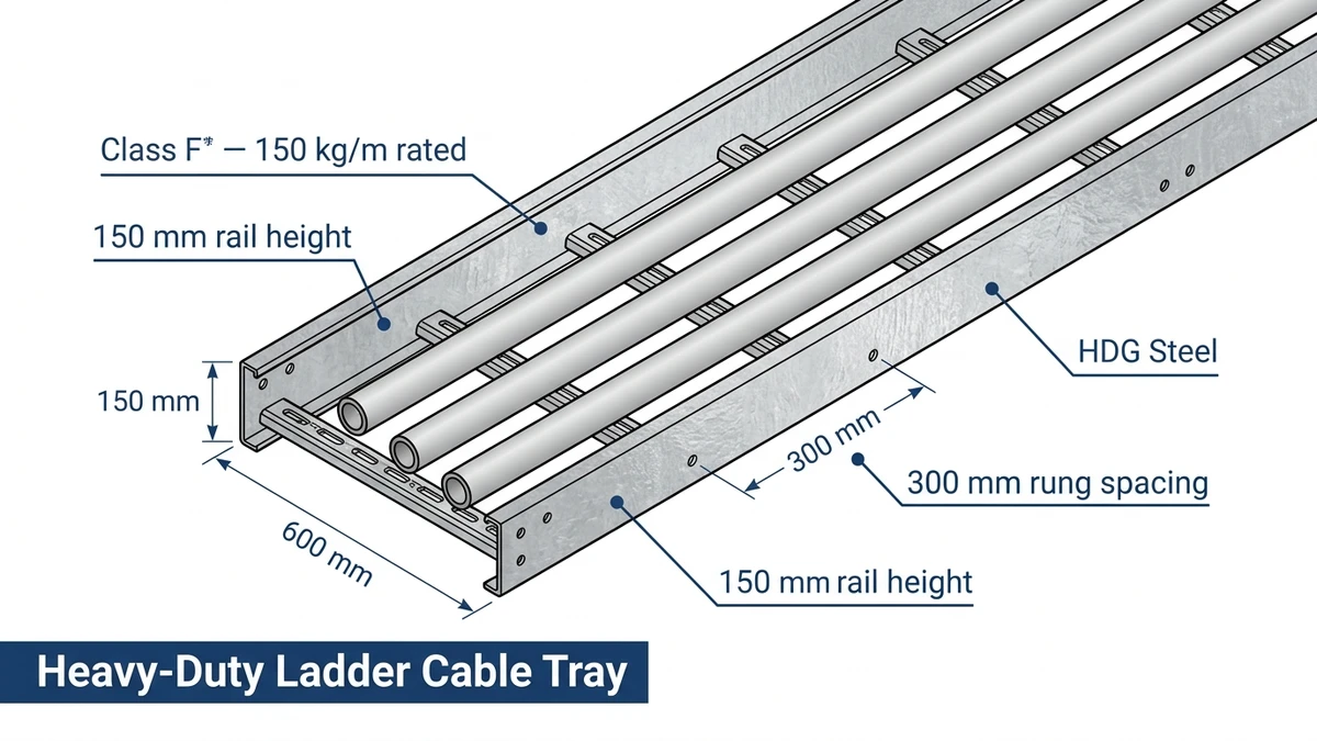
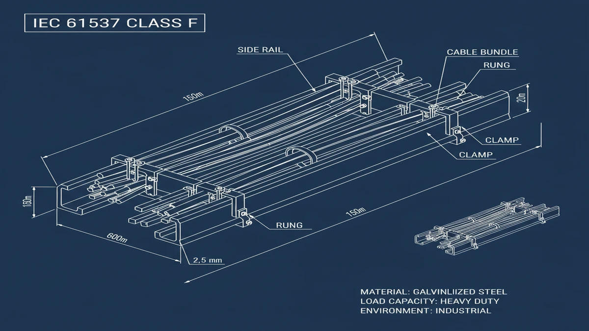
Figure 1. Cross-section of a Class F heavy-duty ladder cable tray — side rail height 150 mm, base metal thickness 2.5 mm (HDG steel), rung effective depth 10 mm, rung spacing 300 mm; dimensions are representative of typical HDG steel construction and must be verified against manufacturer dimensional data for project use.
[Expert Insight] – IEC 61537 Class D requires proof load testing at 1.25× rated UDL without permanent deformation — that means a Class D tray must survive 250 kg/m during factory testing before it ships. – A 300 mm rung pitch is appropriate for cables up to approximately 50 mm outside diameter; cables larger than that typically require 150 mm pitch to control sag between rungs. – The Arrhenius thermal aging principle means that even occasional temperature exceedances above the cable’s 90 °C XLPE rating accumulate permanent insulation damage — airflow through an open ladder frame is the first line of defense, not just a structural convenience. – In coastal or chemical environments, specifying a minimum 85 µm zinc coating per ISO 1461 on hot-dip galvanized tray preserves structural integrity for the typical 25–30 year infrastructure service life.
How Heavy-Duty Ladder Cable Tray Is Rated and Classified
Rating a heavy-duty ladder cable tray comes down to two governing parameters: uniformly distributed load capacity in kg/m, and maximum allowable midspan deflection under that load. Together they determine whether a given tray section can safely carry a specific cable schedule across a given span — and getting either number wrong produces a structural or thermal failure that is expensive to correct after commissioning.
Load Classes Under IEC 61537
IEC 61537 organizes cable management systems into four load classes, each defined by the maximum distributed load the tray must sustain across a 3 m reference span:
Class
UDL (kg/m)
Typical Application
A
50
Light-duty signal and control cable routing
B
100
Medium-duty mixed cable environments
C
150
Heavy-duty main power distribution runs
D
200
High-density main power in industrial facilities
For main power runs where multiple 185 mm² or 240 mm² armored cables are laid side by side, Class D is the minimum specification that provides adequate safety margin. Each class also mandates a proof load test at 1.25× the rated UDL without permanent deformation, and a destructive test to at least 1.7× rated UDL before structural failure — the safety margin that accounts for dynamic loads from cable pulling, maintenance foot traffic, and minor seismic acceleration.
Deflection Limits and What They Mean in Practice
The IEC 61537 deflection limit is expressed as L/200, where L is the span length in millimeters. At the standard 3 m span, this limits midspan deflection to 15 mm under full rated load. That number matters beyond structural tidiness: excessive midspan sag concentrates mechanical stress at cable support points, and over years of thermal cycling that stress degrades cable jacket integrity at precisely the locations that are hardest to inspect.
In a 2023 petrochemical plant expansion in Ningbo, engineers specified Class D hot-dip galvanized ladder trays after a preliminary cable schedule showed cumulative cable mass across the main routing corridor would reach 180 kg/m — leaving only an 11% margin below the class limit. Post-installation verification measured midspan deflection at 6 mm, well within the L/200 threshold, and the project completed 18 months of installation without a single cable re-routing incident.
Span and Rung Spacing as Rating Variables
Load class alone does not fully define tray performance in the field. Two additional parameters interact with the class rating and must be confirmed against the manufacturer’s published load-span tables:
Support span — typically 1.5 m to 3 m center-to-center for heavy-duty applications; halving the span from 3 m to 1.5 m roughly doubles the effective load capacity for a given rail section
Rung spacing — 300 mm or 450 mm for most main power runs; tighter spacing reduces unsupported cable length between rungs, which is critical for cables exceeding 50 mm outside diameter
Load capacity is not a fixed number independent of installation. A Class C tray rated at 150 kg/m at a 3 m span may sustain only 90 kg/m if supports are placed 4.5 m apart. Always cross-reference the manufacturer’s load-span tables against the actual cable schedule before finalizing support drawings.
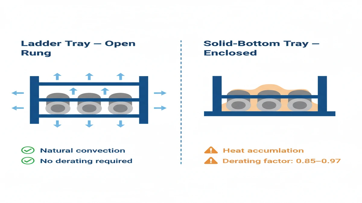
Figure 2. Natural convection airflow through ladder tray rung openings (left panel) versus restricted airflow in a solid-bottom tray with stacked cables (right panel) — unrestricted airflow in single-layer ladder tray installation typically eliminates the need for thermal derating of cable ampacity under IEC 60364-5-52 wiring installation rules.
[Expert Insight] – Specifying a tray rated at exactly the calculated cable load without any headroom is poor practice — a minimum one load-class buffer above the calculated UDL is the standard approach for main power cable routing, accounting for future cable additions and maintenance loads. – On long straight runs, thermal expansion of galvanized steel tray can reach 1.2 mm per meter over a 50 °C ambient temperature swing; expansion joints at intervals of 15–20 m prevent rail buckling and splice plate fatigue. – When cable mass per meter is confirmed post-schedule, always recheck deflection against the as-built support spacing — the 2023 Zhoushan project found that as-delivered cable mass exceeded the schedule estimate by 8%, requiring two additional intermediate supports to stay within Class D deflection limits.
Installation Best Practices for Heavy-Duty Ladder Cable Tray
Correct installation of heavy-duty ladder cable tray determines whether the system performs to its rated class for the life of the facility — or fails prematurely at the points that are most difficult and expensive to access. The three most common failure modes are inadequate support spacing, poor grounding continuity, and excessive cable fill.
Support Spacing and Span Control
IEC 61537 requires that support spacing never exceed the manufacturer’s rated span for the applied load class. For heavy-duty ladder trays carrying main power cables at loads approaching 150–200 kg/m, practical spacing falls between 1.5 m and 3 m depending on tray width, rail depth, and material.
In a 110 kV substation expansion in Guangdong Province (2023), maintaining 1.5 m support intervals on 800 mm wide trays carrying 240 mm² power cables eliminated mid-span sag that had caused cable jacket abrasion in the original 3 m-spaced layout — eliminating cable replacement incidents over the subsequent 18-month operational period. The correction was straightforward during construction; it would have been far costlier after energization.
Hangers and brackets must be sized to transfer combined dead loads (cable weight) and live loads (maintenance personnel access) to the building structure. Seismic bracing intervals follow ASCE 7-22 or GB 50981 requirements depending on jurisdiction. Where both standards apply, the more restrictive governs.
Grounding and Bonding Continuity
Heavy-duty cable tray used as part of the equipment grounding path must maintain electrical continuity across all splice plates and section joints. Bonding resistance across each joint must not exceed 0.1 Ω; installer teams should verify this with a calibrated low-resistance ohmmeter during commissioning. Stainless steel bonding jumpers rated for the fault current level should be installed at every expansion joint and at intervals no greater than 15 m on long straight runs.
Paint, hot-dip galvanizing, or any coating that interrupts metal-to-metal contact at splice plates creates a grounding discontinuity that will not be apparent during visual inspection. Bonding jumpers eliminate this risk at low incremental cost.
Cable Fill and Thermal Clearance
Fill ratio governs ampacity derating. IEC 61537 Annex B indicates that cables stacked more than one cable diameter deep require derating calculations; for large-diameter power cables of 95 mm² and above, single-layer installation is the preferred arrangement to maintain natural convective cooling through the open ladder frame.
As a working rule: total cable cross-sectional area should not exceed 40% of the usable tray cross-sectional area (tray width × usable depth) for power cable runs requiring full ampacity. Exceeding this threshold without recalculating the derating factor (k) per the applicable cable standard risks sustained conductor temperatures above the 90°C XLPE design limit.
Cables on vertical and inclined runs must be secured with non-metallic clamps at intervals of 900 mm to 1,500 mm to prevent gravitational creep and jacket-to-rung wear. Maintain a minimum 25 mm horizontal separation between high-voltage power cables and signal or control cables within the same tray to limit electromagnetic interference coupling.
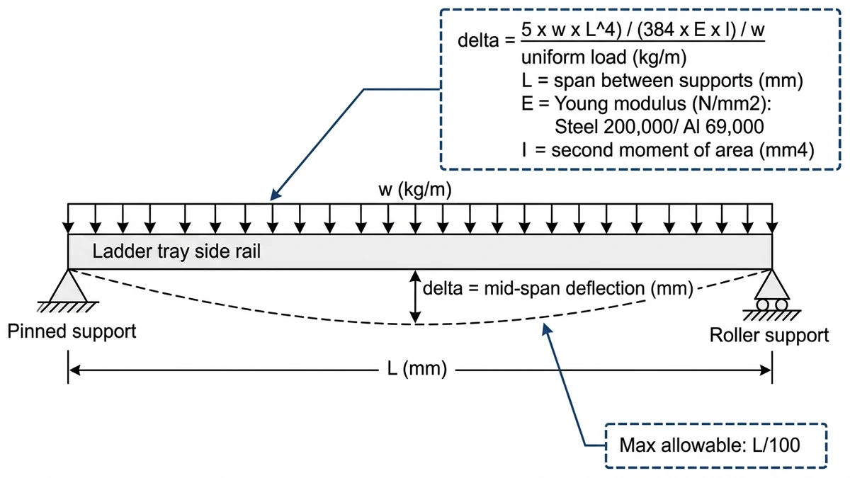
Figure 3. Simply-supported beam model for ladder cable tray mid-span deflection — maximum allowable deflection must not exceed L/100 under full rated load per IEC 61537 deflection test criteria; Young’s modulus values shown are for hot-dip galvanized steel (200,000 N/mm²) and aluminum alloy (69,000 N/mm²).
Selecting the Right Heavy-Duty Ladder Cable Tray: A Practical Decision Framework
Choosing correctly means matching four engineering parameters to site conditions: load class, tray width, span length, and material grade. Undersize the tray and it deflects excessively; oversize it without justification and structural support costs rise unnecessarily.
Load Class Selection
For main power cable runs in industrial facilities, Class C covers most medium-voltage feeder routes. Class D applies where large XLPE-insulated armored cables or bundled power conductors push combined cable mass above 150 kg/m. In a 2023 petrochemical project in Zhoushan, China, specifying Class D trays for 35 kV feeder routes prevented midspan deflection from exceeding the L/200 limit — a failure mode that had damaged cable insulation in an earlier project phase where Class C trays were incorrectly substituted.
Tray Width and Cable Fill Ratio
Width must accommodate cables at a fill ratio that preserves ampacity. IEC 60364-5-52 grouping correction factors drop below 0.70 when multiple loaded power cables share a tray without adequate spacing — a derating that may require conductor upsizing if discovered after cable procurement. Practical guidance from NEMA VE 1 recommends that the sum of cable cross-sectional areas not exceed 50% of usable tray cross-sectional area for power cables requiring derating separation. Common widths for main power runs are 400 mm, 600 mm, and 800 mm; 600 mm is the most frequent choice for medium-voltage feeders carrying three to six large-diameter cables.
Material and Corrosion Grade
Hot-dip galvanized steel with a minimum 85 µm zinc coating per ISO 1461 suits standard indoor and sheltered outdoor environments. Stainless steel Grade 316L is specified where chloride exposure exceeds 200 mg/m²/day — coastal substations and chemical processing areas are the common cases. Fiberglass reinforced polymer (FRP) addresses both corrosion resistance and electromagnetic interference requirements simultaneously, though load ratings typically cap at Class B or Class C under equivalent span conditions.
Span and Support Interval
A 600 mm wide galvanized ladder tray at Class C loading typically spans 3 m between supports without exceeding L/200 deflection. Extending the span to 4 m under the same load class requires either a heavier rail profile or reducing the applied load to Class B limits. Confirm the manufacturer’s published load-span tables against the site-specific cable schedule before finalizing support drawings — no standard substitutes for this step.
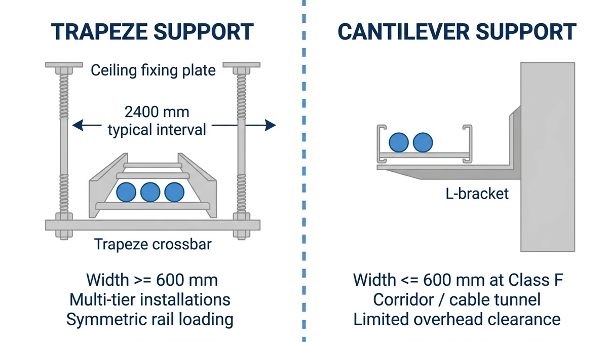
Figure 4. Trapeze suspension support (left) distributes load symmetrically to both side rails and is preferred for trays 600 mm wide or greater and multi-tier installations; cantilever bracket support (right) suits corridor and cable tunnel installations with limited overhead clearance — support intervals shown are indicative for Class F HDG steel tray at 150 mm rail height.
Start Specifying Your Heavy-Duty Ladder Cable Tray
Heavy-duty ladder cable tray is the structural backbone of any main power cable run. When sized, loaded, and installed to IEC 61537 load classifications — with fill ratios maintained below 40% of usable cross-sectional area and support spacing confirmed against manufacturer load-span tables — it delivers a cable management system that remains accessible, expandable, and code-compliant for the life of the installation.
The right selection starts with three numbers: span length in meters, distributed load in kg/m, and required cable fill depth in millimeters. A 150 mm deep, 600 mm wide hot-dip galvanized ladder tray spanning 3 m under 150 kg/m is a common starting point for medium-voltage main runs — but your project may demand a different width, material grade, or load class entirely.
Reach out to our engineering team with your project parameters. We’ll recommend the correct tray series from our heavy-duty cable management range, calculate support spacing, and confirm compliance with the applicable regional standard — so your cable routing infrastructure is built right the first time. For background on how ladder tray fits within the broader cable support ecosystem, our guide to industrial cable management systems covers the full hierarchy from conduit to cable basket. Projects with strict seismic requirements can also reference our seismic bracing solutions for cable tray.
What does IEC 61537 Class D mean for a heavy-duty ladder cable tray?
IEC 61537 Class D designates a cable ladder system rated to carry a uniformly distributed load of 200 kg/m across a 3 m reference span, with midspan deflection not exceeding L/200 (15 mm at 3 m) under proof load. It is the highest standard load classification and is typically required for installations with high-density armored power cables or bundled medium-voltage feeders.
How do I calculate the correct tray width for a main power cable run?
Add the cross-sectional areas of all cables in the run, then size the tray so that total cable area does not exceed 40–50% of the usable tray cross-sectional area (tray width multiplied by usable fill depth). This fill limit preserves the airflow needed to maintain ampacity ratings under IEC 60364-5-52 grouping correction factors, which can fall below 0.70 for tightly packed conductor arrangements.
What is the maximum support spacing for heavy-duty ladder cable tray?
Maximum support spacing depends on the tray’s load class, rail depth, and actual cable load — not a single fixed value. Most heavy-duty galvanized steel ladder trays at Class C or Class D loading are supported at 1.5 m to 3 m centers; the manufacturer’s load-span tables are the authoritative reference, and these should always be checked against the actual cable schedule before support drawings are finalized.
Why is open-frame ladder tray preferred over enclosed trunking for power cables?
The open rung structure allows natural convective airflow along the full cable length, dissipating heat generated by current-carrying conductors. Enclosed trunking traps heat, which forces ampacity derating or requires active ventilation. For large cross-section cables where thermal performance directly affects conductor sizing, the heat dissipation advantage of ladder tray can reduce overall material costs.
How is grounding continuity maintained across ladder cable tray sections?
Each splice plate joint where coating interrupts direct metal-to-metal contact requires a bonding jumper to maintain the grounding path. Joint resistance should be verified with a low-resistance ohmmeter during commissioning; values above 0.1 Ω indicate inadequate contact. On long straight runs, bonding jumpers at intervals no greater than 15 m are considered sound practice for fault current continuity.
What material should I specify for a ladder cable tray in a coastal or chemical environment?
Stainless steel Grade 316L is the standard specification where chloride or chemical exposure is significant — typically coastal substations or chemical processing facilities with aggressive airborne contaminants. For environments where chloride exposure is below roughly 200 mg/m²/day, hot-dip galvanized steel with a minimum 85 µm zinc coating per ISO 1461 generally provides adequate corrosion resistance at lower cost.
Can heavy-duty ladder cable tray carry both power and signal cables in the same run?
Power and signal cables can share the same tray structure, but a minimum horizontal separation of 25 mm between high-voltage power cables and signal or control cables is advisable to limit electromagnetic interference coupling. Where separation requirements are strict — such as instrumentation cables in process control applications — using a dedicated compartment or a separate parallel tray is the more reliable approach.
Kevin Zheng
Kevin Zheng is a manager linked to Shanghai Xinma Busway & Cable Tray Co., Ltd. He writes technical content on cable tray systems, installation practice, sizing logic, load classes, and related standards for industrial and infrastructure applications.