What Is a Cable Tray? Definition, Function, and Core Engineering Role
A cable tray is a rigid, factory-fabricated structural system used to support and route electrical cables, fiber optic lines, and instrumentation wiring across buildings, industrial plants, and infrastructure facilities. In 2026, cable trays remain the dominant open cable management system for installations requiring frequent access, high cable density, or long routing spans exceeding 3 m between supports.
Governed by IEC 61537 (Cable Management — Cable Tray Systems and Cable Ladder Systems), cable trays must meet defined load classes ranging from 50 kg/m to 200 kg/m, each with corresponding maximum midspan deflection limits calculated as a ratio of span length. This standard, published by the International Electrotechnical Commission, sets the global baseline for tray geometry, material testing, and load classification.
What a Cable Tray Actually Does
A cable tray serves three engineering functions simultaneously: mechanical support, cable organization, and environmental protection. Unlike conduit, which encloses cables inside a sealed tube, a cable tray holds cables in an open or ventilated structure — allowing heat dissipation, visual inspection, and rapid field modifications without dismantling the system. This openness is precisely why ampacity derating factors for cables in trays differ from those in conduit; heat accumulation is reduced, and conductors can typically carry closer to their rated current.
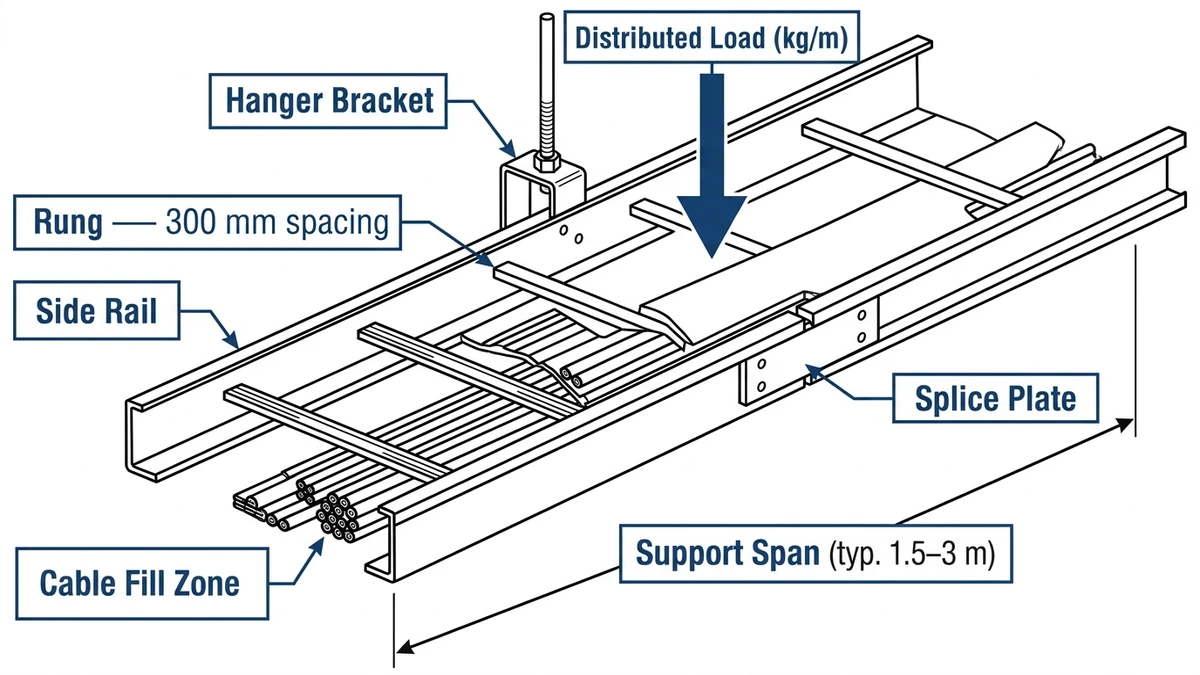
Core Components of a Cable Tray System
A complete cable tray system consists of three primary elements:
Straight sections — the main routing segments, typically available in lengths of 3 m or 6 m
Fittings — horizontal bends, vertical rises, tees, and reducers that redirect cable routing
Support hardware — trapeze hangers, wall brackets, or floor-mounted supports spaced at 1.5 m to 3 m intervals depending on load class
These components combine to form a continuous cable management pathway from source to termination point.
What Cable Trays Are Not
Cable trays are not raceways in the conduit sense — they do not provide mechanical protection equivalent to rigid metal conduit. Cables installed in open cable trays must carry their own rated insulation and, where required, flame-retardant jackets compliant with IEC 60332 or equivalent national standards.
Where the Definition Matters in Practice
In a 2024 semiconductor fabrication plant expansion in Suzhou, China, the engineering team selected ladder-type cable trays for process-area power routing. The decision turned on the IEC 61537 distinction between “open” and “enclosed” cable management: because the facility’s cable schedules included 240 mm² power cables with a mass of approximately 4.8 kg/m, open ladder trays rated at 150 kg/m (Class C under IEC 61537) were specified to maintain fill-ratio compliance and allow thermal dissipation along the cable jacket — a critical factor in preventing ampacity derating in dense cable runs.
That distinction — open, accessible, load-rated support versus enclosed mechanical protection — is the foundation of every cable tray selection decision covered in this article.
[Expert Insight]
– IEC 61537 Class C (150 kg/m) is the most commonly specified load class in heavy industrial projects; many engineers default to Class B and later require costly upgrades when late-stage cable additions push loads past 100 kg/m.
– Open-tray installations reduce ampacity derating compared to conduit, but only when cable spacing is maintained — bundled cables touching each other negate much of the thermal benefit.
– The IEC 61537 deflection limit of L/200 at midspan is a serviceability criterion, not a safety margin; exceeding it does not mean imminent collapse, but it does signal that the support spacing or load class must be revised.
– Where a cable tray also serves as an equipment grounding conductor, splice plate continuity — not just tray material — determines whether the ground path meets code.
Source-backed engineering note: Cable tray selection should be tied to recognized installation and product standards rather than only visual tray type. For product testing and load classification, buyers commonly reference IEC 61537 cable management and cable tray systems or NEMA VE 1 metal cable tray systems. For electrical installation, grounding, ampacity, and wiring-method decisions, the project team should align the tray specification with the applicable electrical code and consultant drawings, such as NFPA 70 / NEC where it applies.
Where Cable Trays Are Used
Cable trays appear across nearly every sector of modern infrastructure. The engineering rationale, however, differs sharply by environment — and understanding those differences is what separates a well-specified system from one that fails within its first maintenance cycle.
Power Generation and Industrial Plants
Heavy industrial facilities — refineries, chemical plants, and power stations — represent the most demanding cable tray environments. Cable routing in these settings must accommodate large-diameter power cables (often 150 mm² to 400 mm² cross-section) alongside instrument and control cables, typically on separate trays to prevent electromagnetic interference. In a 2024 petrochemical plant expansion in Shandong Province covering approximately 18,000 m² of process area, ladder-type cable trays in hot-dip galvanized steel were specified at load Class C (≥ 150 kg/m per IEC 61537) to handle the combined cable fill, with 1.5 m support spacing selected to keep midspan deflection under 12 mm.
A separate 2024 combined-cycle power plant project in Guangdong Province — with 42,000 m of installed tray length — demonstrated what large-scale planning unlocks: switching from conduit to ladder-type cable tray reduced installation labor hours by 28% and allowed cable pull-in teams to complete each 50 m bay in under 4 hours. Both projects confirm why ladder tray dominates heavy industrial specification in China.
Data Centers and IT Infrastructure
Data centers prioritize flexibility and cable density. Ventilated tray and wire mesh tray systems dominate because open construction supports airflow around high-density Category 6A, fiber optic, and power distribution cables. Fill ratio — the proportion of cable cross-sectional area to usable tray interior — is the governing design parameter here, typically capped at 40–50% per NEMA VE 1 guidelines to allow heat dissipation and accommodate future cabling additions.
Commercial Buildings and Offices
In commercial construction, cable trays route low-voltage systems including structured cabling, fire alarm wiring, and building automation networks above suspended ceilings. Perforated tray in powder-coated steel or aluminum is standard because it balances cost, aesthetics, and adequate cable support. Tray widths of 150 mm to 300 mm cover most office-scale deployments.
Transportation Infrastructure
Rail transit tunnels, airports, and highway tunnels use cable trays extensively for traction power, signaling, and communications cables. Fire-rated coatings or stainless steel grades are frequently specified where evacuation safety is a regulatory requirement. Seismic bracing follows ASCE 7 or equivalent national standards in seismically active corridors.
Renewable Energy Installations
Solar farms and wind turbine arrays rely on cable tray for DC collection circuits and AC aggregation runs across large ground areas. UV-stabilized fiberglass reinforced plastic (FRP) trays are increasingly selected for outdoor photovoltaic fields because they are non-conductive, corrosion-resistant, and eliminate grounding complexity for DC systems operating at up to 1,500 V DC.
[Expert Insight]
– In petrochemical and offshore environments, the expected service life difference between hot-dip galvanized steel and uncoated steel can exceed 15 years — but only when the zinc coating thickness meets ISO 1461 minimums at cut edges and field welds, which are the first failure points observed in practice.
– FRP trays eliminate grounding path complexity for high-voltage DC photovoltaic systems, but field crews must be trained on cut-edge sealing; exposed FRP fibers absorb moisture and reduce mechanical strength over time in high-humidity outdoor environments.
– Wire mesh trays used in data center overhead routing typically weigh under 3 kg/m for 300 mm wide sections — a meaningful advantage when cumulative dead load calculations determine whether existing structural steel requires reinforcement.
Quick Comparison: Cable Tray Types, Materials, and Engineering Fit
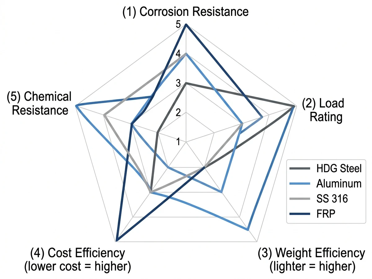
Cable tray systems are manufactured from four primary materials — steel, aluminum, fiberglass-reinforced plastic (FRP), and stainless steel — each selected based on environmental exposure, load requirements, and installation cost. Getting material selection right at the specification stage is far less expensive than a field replacement driven by premature corrosion or mechanical overload.
Steel (Hot-Dip Galvanized and Pre-Galvanized)
Steel is the most widely used cable tray material in industrial and commercial construction. Hot-dip galvanized steel provides a zinc coating typically 45–85 µm thick per ISO 1461, offering strong corrosion resistance in moderate environments. Pre-galvanized (mill-galvanized) sheet steel carries a thinner coating — typically 7–20 µm — and suits indoor, dry installations where cut-edge exposure is minimal.
In a 2024 petrochemical plant expansion in Shandong Province, hot-dip galvanized ladder cable trays spanning 3 m at 600 mm width handled a distributed cable load of 120 kg/m without exceeding the IEC 61537 Class C deflection limit of L/200, confirming steel’s structural advantage in heavy-duty cable management system applications.
Aluminum
Aluminum cable trays weigh approximately 65% less than equivalent steel trays, making them preferred for overhead installations where support-structure dead loads must be minimized. Aluminum alloy 6063-T5 or 6061-T6 is typical, providing good atmospheric corrosion resistance without additional coating. Aluminum is, however, unsuitable for direct contact with concrete or alkaline materials without a protective separation layer.
Fiberglass-Reinforced Plastic (FRP)
FRP cable trays are non-conductive, non-magnetic, and highly resistant to corrosive chemicals — making them the standard choice in wastewater treatment plants, offshore platforms, and chemical processing facilities. They are not suitable for continuous service above 130°C.
Stainless Steel
Stainless steel (typically Grade 304 or Grade 316) is specified where hygiene standards, high humidity, or aggressive chemical exposure rules out galvanized steel. Grade 316 contains molybdenum, improving resistance to chloride-induced pitting — critical in food processing or coastal marine installations. Stainless steel trays typically cost 3–5× more than hot-dip galvanized equivalents, so their use is generally limited to high-consequence zones rather than full system runs.
How to Select the Right Cable Tray for Your Application
Selecting the correct cable tray type begins with four engineering parameters: load capacity, environmental exposure, cable fill requirements, and routing geometry. Matching these variables to available tray types prevents under-specification failures and eliminates unnecessary material cost.
Step 1: Determine the Required Load Class
Begin by calculating the total cable mass per linear meter of tray run. Sum the weight per meter of every cable routed through the tray — including future spare capacity, typically 20–25% of the initial fill — then identify the IEC 61537 load class that exceeds that figure.
IEC 61537 classifies cable trays from Class A (50 kg/m, light duty) through Class D (200 kg/m, heavy industrial), with intermediate classes at 100 kg/m and 150 kg/m. In a 2024 petrochemical expansion project in Ningbo, China, the cable routing team initially specified Class B trays at 100 kg/m for a motor control cable bundle. When bundle mass recalculation — accounting for armored 35 mm² power cables added late in design — pushed the load to 118 kg/m, the specification was revised to Class C before procurement, avoiding a costly mid-installation change order.
Step 2: Match Tray Type to Cable Mix
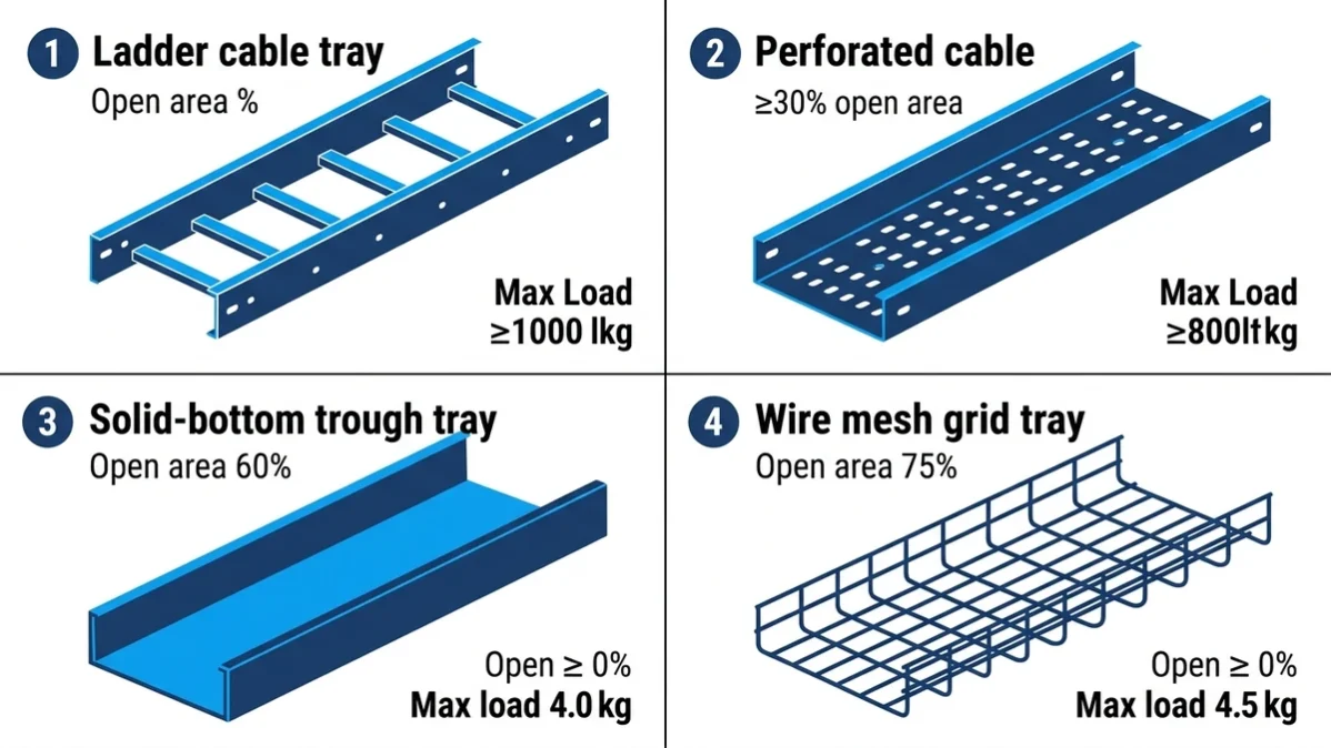
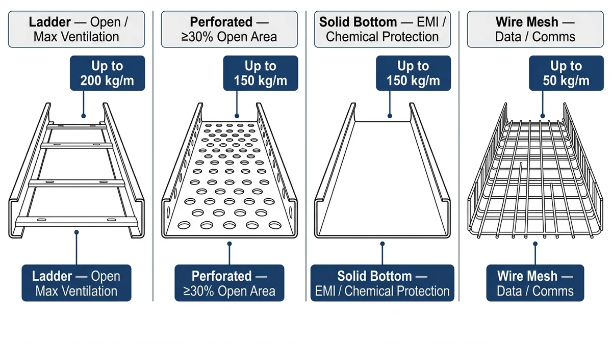
Different tray types serve different cable populations:
Ladder trays suit power cables 16 mm² and larger where open ventilation reduces ampacity derating under IEC 60364-5-52
Perforated bottom trays work well for mixed power and instrumentation cable runs where moderate support is needed at spans up to 3 m
Solid-bottom trays protect signal and data cables from mechanical damage and electromagnetic interference in control rooms
Wire mesh trays fit data center overhead routing where flexibility and low plenum weight — typically under 3 kg/m for 300 mm wide sections — are priorities
Step 3: Match Material to Environment
Once the load class is defined, filter by environmental classification:
Indoor, dry — Pre-galvanized steel is cost-effective and sufficient
Outdoor or coastal — Hot-dip galvanized steel (minimum 85 µm coating per ISO 1461) or 316L stainless steel resists salt fog and UV degradation
Chemical or corrosive process areas — FRP trays resist acids, alkalis, and chlorinated solvents without metallic corrosion risk
Data center and plenum — Aluminum trays minimize electromagnetic interference and reduce structural dead load
Step 4: Verify Fill Ratio and Tray Width
Cable fill ratio — the proportion of total cable cross-sectional area to usable tray interior area — should not exceed 50% for power cables, as required under NEC Article 392 for multiconductor cables in ladder and ventilated trough trays. Exceeding this limit impairs heat dissipation and forces ampacity derating.
For a 300 mm wide tray with a usable interior depth of 100 mm, the maximum allowable fill area is 15,000 mm² (applying the 50% rule to a nominal 100 mm usable height). If the cable bundle cross-section exceeds this, select the next standard width — typically 450 mm or 600 mm.
Step 5: Account for Routing Geometry
Complex routes with frequent direction changes favor narrower perforated or wire mesh trays, which accommodate tighter bend radii. Straight horizontal runs in substations or cable tunnels favor wide ladder trays (up to 900 mm) that minimize support bracket count and installed labor cost per meter.
Applying these five steps in sequence — load class, tray type, material, fill, geometry — ensures the selected cable management system is both structurally adequate and code-compliant before a single bracket is ordered.
Buyer Verification Checklist for Cable Tray Type and Material Selection
Request load tables that state the test span, tray width, and allowable deflection.
Confirm whether the quoted system includes fittings, covers, couplers, hold-down clamps, grounding jumpers, and support brackets.
Ask for coating or material documentation, especially for hot-dip galvanized, stainless steel, aluminum, or FRP tray.
Check whether the selected tray family has matching accessories for bends, tees, reducers, and vertical transitions.
Compare the installed route cost, not only the straight-tray unit price.
For export or EPC projects, review packing method, labels, drawing references, and inspection records before shipment.
Cable tray systems are not passive structures — they carry energized cables and must be engineered with electrical performance in mind. Two core electrical factors govern cable tray design: ampacity derating and equipment grounding continuity.
Ampacity Derating in Cable Trays
When current-carrying conductors are grouped together in a cable tray, heat generated by each cable accumulates within the fill area. This mutual heating effect reduces the current-carrying capacity of every cable in the group — a phenomenon defined as ampacity derating.
Under NEC Article 392, multiconductor cables installed in cable trays must have their ampacity reduced based on fill area and spacing. In a 300 mm wide ladder tray fully loaded with 75 mm² cables at a 40 °C ambient temperature, derating factors can reduce allowable ampacity by 15–30% compared to free-air ratings. Engineers must account for this in conductor sizing before specifying tray fill.
Maintaining cable spacing — a minimum 6.35 mm (¼ inch) between single-conductor cables — is the most practical method to limit thermal buildup and reduce the derating penalty.
Grounding and Bonding Requirements
Cable trays used as equipment grounding conductors (EGC) must meet minimum cross-sectional area requirements to provide a reliable fault return path. Steel trays with a minimum 1.5 mm nominal thickness and continuous splice connections qualify as EGCs under applicable electrical codes, provided splice plates maintain metal-to-metal contact throughout the run.
Aluminum trays require careful attention at splice joints, as aluminum oxide film forms on exposed surfaces and increases contact resistance. In a 2023 petrochemical plant expansion in Shandong Province, untreated aluminum splice joints introduced ground path resistance above 0.1 Ω, causing nuisance ground-fault trips. Applying conductive joint compound at each splice reduced resistance to below 0.01 Ω and resolved the fault detection issue — a straightforward fix, but one that cost several days of diagnostic labor before the root cause was identified.
Separation of Circuit Types
IEC 61537 and industry practice both recommend physical separation between power cables and signal or instrumentation cables within cable tray systems. A minimum 200 mm separation distance — or use of a dedicated barrier tray — prevents electromagnetic interference from high-voltage conductors degrading low-voltage signal integrity. In sensitive process control environments, separate cable routing systems are often the engineering standard of choice.rnrn—
Frequently Asked Questions
What is the difference between a cable tray and conduit?
A cable tray is an open structural support system that holds cables along an accessible pathway, while conduit is a sealed tube that encloses cables for mechanical protection. Cable trays allow faster installation, easier future modifications, and reduced ampacity derating compared to enclosed conduit systems.
How is cable tray load class determined under IEC 61537?
Load class is determined by calculating the total distributed mass of cables per linear meter of tray run — including a 20–25% allowance for future cable additions — then selecting the next IEC 61537 class above that figure, ranging from Class A at 50 kg/m through Class D at 200 kg/m.
What fill ratio should I use when sizing cable tray width?
A fill ratio at or below 50% of the tray’s usable cross-sectional area is the general guideline for power cables, based on NEC Article 392 requirements for multiconductor cables in ladder and ventilated trough trays; staying below this threshold preserves heat dissipation capacity and leaves room for future cable additions.
Which cable tray material works best in corrosive environments?
Fiberglass-reinforced plastic (FRP) trays are typically selected for chemical processing, offshore platforms, and wastewater facilities because they resist acids, alkalis, and chlorinated solvents without the corrosion risk associated with metallic trays; Grade 316 stainless steel is the alternative where structural load requirements exceed FRP capabilities.
Why does cable spacing inside a tray affect ampacity?
Cables touching or closely bundled together trap heat between conductors, raising operating temperature and reducing the safe current-carrying capacity of each cable; maintaining a minimum 6.35 mm gap between single-conductor cables allows air circulation and limits the mutual heating effect that drives ampacity derating calculations.
How do I ensure a cable tray qualifies as an equipment grounding conductor?
Steel trays with a minimum nominal thickness of 1.5 mm and continuously bonded splice plates can qualify as equipment grounding conductors under applicable electrical codes; aluminum trays require conductive joint compound at each splice to prevent aluminum oxide film from introducing resistance above acceptable ground-path limits.
What tray type is recommended for data center overhead cable routing?
Wire mesh trays are widely used in data center overhead installations because they weigh under 3 kg/m for 300 mm wide sections, accommodate frequent cable additions without full tray access, and support the high-density routing of Cat6A, fiber optic, and power distribution cables within the 40–50% fill ratio guidelines in NEMA VE 1.
Kevin Zheng
Kevin Zheng is a manager linked to Shanghai Xinma Busway & Cable Tray Co., Ltd. He writes technical content on cable tray systems, installation practice, sizing logic, load classes, and related standards for industrial and infrastructure applications.