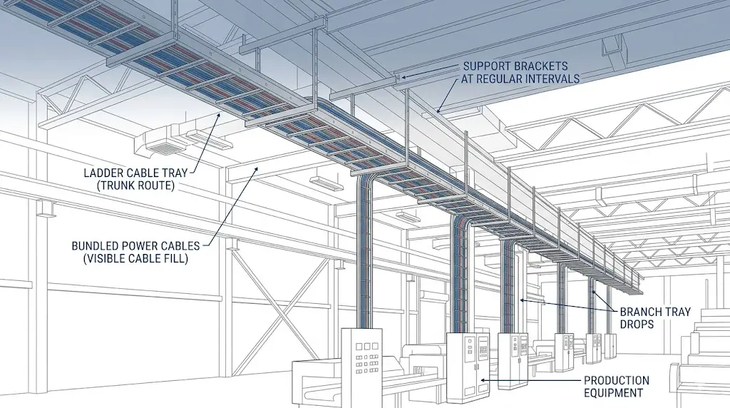
Cable tray systems are structured cable management infrastructures used to support, route, and protect electrical power cables, control cables, and data cables in industrial and commercial buildings. Wherever large volumes of conductors must travel predictable paths — across ceilings, along walls, through vertical risers — cable trays replace individual conduit runs with an open, accessible, and scalable routing solution. The engineering decisions made at specification stage directly determine installation labor, long-term maintenance cost, and compliance with IEC 61537, NEC, and NEMA VE 1 requirements.
A cable tray system’s primary job is to carry distributed cable weight across defined spans without exceeding allowable deflection. Per IEC 61537, load capacity is classified from Class A (50 kg/m) to Class D (200 kg/m), with maximum midspan deflection held to L/200 under proof load conditions. That structural function alone makes cable tray the preferred cable management system whenever cable counts make individual conduit runs economically or logistically impractical.
In a 2023 pharmaceutical manufacturing facility in Suzhou, China — approximately 18,000 m² of production floor — ladder-type cable trays at 600 mm width with 3 m support spacing carried an average load of 85 kg/m across 12 km of cable runs. The installation reduced cable routing labor hours by approximately 28% compared to the conduit-based baseline, based on contractor time-log data.
Secondary Function: Environmental Separation and Cable Organization
Beyond load support, cable trays enforce physical separation between cable categories. Industrial facilities typically route power cables (600 V or higher) in dedicated trays separated by at least 200 mm from instrumentation or signal cable trays, consistent with IEC 61000-5-2 electromagnetic compatibility installation guidance . This separation prevents electromagnetic interference from distorting low-voltage sensor signals — a critical requirement in process control environments such as oil refineries, water treatment plants, and semiconductor fabs.
The open-top design of most cable tray systems also simplifies thermal management: cables dissipate heat more effectively in open trays than in enclosed conduit, directly affecting ampacity derating factors under NEC 310.15 or IEC 60364-5-52 installation method classifications.
Where Cable Trays Appear in Buildings
Cable tray systems are deployed across three broad facility categories:
Industrial plants — motor control centers, transformer vaults, and process equipment interconnection
Commercial buildings — data centers, office raised-floor environments, and mechanical/electrical rooms
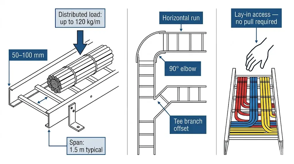
Figure 1. Ladder cable tray performing three simultaneous engineering functions: distributed load bearing on side rails (up to 120 kg/m at 1.5 m span), continuous routing path through elbow and tee fittings, and open-top lay-in access for cable inspection and addition without system breach.
[Expert Insight]
IEC 61537 load classes are proof-load ratings, not working-load limits; most engineers apply a 1.25 safety margin on top of the rated class, which means a Class C (150 kg/m) tray is typically specified for calculated loads up to 120 kg/m.
Open-top ladder tray provides the highest ampacity because free air circulation around cables reduces the need for derating — a meaningful cost advantage when conductor sizing is driven by thermal limits rather than voltage drop.
Tray systems double as bonding conductors in many installations; verify that splice connector resistance meets the ≤ 0.1 Ω end-to-end continuity requirement before finalizing the earthing design.
Where Cable Tray Systems Are Installed
Field conditions — not catalog defaults — determine which cable management system is appropriate. The core selection trigger is simple: when cable counts exceed what conduit can handle economically, or when future access and modification are priorities, cable tray is the right infrastructure. But the environment where that tray lives shapes every other decision.
Industrial Facilities
In petrochemical plants, refineries, and manufacturing floors, cable trays typically run overhead along pipe racks or structural steel at 3–6 m above grade. These environments demand trays rated for continuous operating temperatures up to 120 °C and corrosion-resistant finishes — hot-dip galvanized steel or fiberglass-reinforced polymer (FRP) — to withstand chemical exposure and humidity.
In a coal-fired power station retrofit in Shandong Province (2023), replacing aging conduit runs with 400 mm-wide stainless steel ladder trays across a 1,200 m main cable route reduced installation labor by 28% and added 40% more cable capacity without structural rework.
Commercial and Data Center Buildings
In high-rise office towers and Tier III/IV data centers, wire tray and cable ladder systems are installed above suspended ceilings, in raised-floor voids, and in dedicated electrical rooms. Data center deployments are density-driven: a single 600 mm-wide ladder tray can carry upward of 150 kg/m of power and data cables simultaneously, provided the load class matches IEC 61537 Class C or Class D. Power and low-voltage data cables are segregated into parallel trays with a minimum 300 mm horizontal clearance to limit electromagnetic interference.
Transportation and Tunnel Infrastructure
Rail transit tunnels, airport terminals, and highway tunnels rely on cable tray systems to manage traction power feeds, signaling cables, and emergency lighting circuits along extended linear routes — often spanning several kilometers. FRP or aluminum trays are preferred in tunnel applications where weight loading on tunnel liners is restricted to under 20 kg/m² and where condensation and groundwater ingress are constant field conditions.
Vertical Risers and Utility Shafts
Vertical cable tray runs in building risers carry cables between electrical rooms and distribution floors. Riser applications require project-specific cleat or support spacing based on cable weight, route height, and the cable manufacturer’s installation limits to prevent slippage under self-weight over multi-story heights.
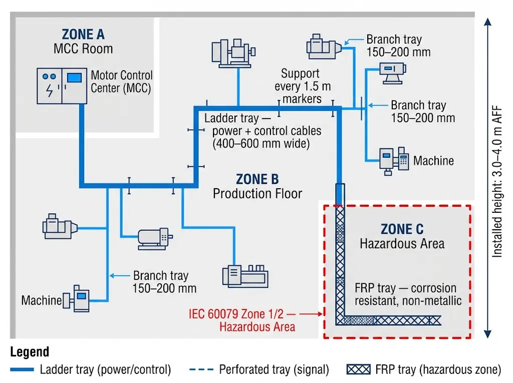
Figure 2. Cable tray routing map for a representative industrial manufacturing plant: ladder tray trunk routes (400–600 mm wide) run from the motor control center to production zone branch points; FRP trays serve IEC 60079 Zone 1/2 hazardous areas where corrosion and chemical exposure demand non-metallic construction.
[Expert Insight]
Tunnel installations frequently specify aluminum trays over steel not just for weight savings but because aluminum’s natural oxide layer provides adequate corrosion resistance in high-humidity environments without additional coating maintenance.
In vertical riser applications, cable cleats also perform a fire-containment function — properly spaced cleats limit cable movement during a fault event, reducing fire propagation between floors.
Data center cable routing benefits from a documented pathway matrix: mapping each tray run to a rack row and fill tier at design stage prevents the common problem of a fully loaded tray discovered only when a new cable circuit needs adding.
Cable Tray Applications Across Industrial Sectors
The cable management system that performs well in a data center ceiling corridor faces entirely different demands in a polypropylene plant or a coastal desalination facility. Understanding what specific field conditions exist — temperature, chemical exposure, vibration, fill density — is the only reliable way to translate a load class and material spec into a tray that lasts its intended service life.
Manufacturing and Heavy Industry
In automotive assembly plants and petrochemical refineries, cable trays carry power distribution cables, instrumentation wiring, and control circuits simultaneously across large floor areas. A 2023 retrofit at a 120,000 m² automotive stamping facility in Wuhan replaced conduit runs with hot-dip galvanized ladder cable trays rated to IEC 61537 Class D (200 kg/m), cutting installation labor by approximately 28% and reducing rerouting time during line changes from 4 days to under 18 hours. Tray widths of 600 mm and 900 mm accommodated power, control, and instrumentation cables on separate levels, with segregation distances of at least 150 mm maintained between voltage classes.
Control and Instrumentation Cable Segregation
Instrument and control cables — including 4–20 mA analog signals and fieldbus wiring — require physical separation from high-voltage power cables to prevent electromagnetic interference. IEC 61537 recommends a minimum 300 mm separation between power and instrument trays, or the use of solid-bottom trays with metallic dividers when parallel routing within 150 mm is unavoidable. In practice, engineers assign dedicated tray tiers: power cables on the upper level, control cables on the intermediate level, and fiber optic or data cables on the lowest tier closest to equipment panels.
Data Centers and Telecommunications Facilities
Data centers demand high cable density and frequent reconfiguration. Ladder cable trays at 600 mm width spanning 2.4 m between supports are common above raised floors and in overhead cable corridors. Fill ratio management is critical: industry practice limits cable fill to 40–50% of the tray cross-sectional area to maintain ampacity derating margins and allow future cable additions without tray replacement. In a 4,800 m² hyperscale data hall completed in Shenzhen (2024), perforated aluminum trays spanning 1.5 m between support brackets sustained cable loads of 35 kg/m with midspan deflection measured at under 6 mm — satisfying IEC 61537 Class B proof load requirements.
Commercial Buildings and Healthcare Facilities
In office towers, hospital campuses, and transit stations, cable trays route low-voltage systems — fire alarm circuits, nurse call wiring, security cabling, and building automation system (BAS) wiring — through ceiling plenums and riser shafts. Return-flange solid-bottom trays are frequently selected in these environments because they provide EMI shielding and meet fire-rated plenum requirements. In a hospital retrofit in Guangzhou (2022), replacing J-hooks with 150 mm solid-bottom cable trays in the ICU wing reduced cable sag-related faults over a 12-month post-installation audit period and simplified compliance documentation under local electrical inspection protocols.
Outdoor, Corrosive, and Hazardous Locations
Petrochemical plants and wastewater treatment facilities require cable trays rated for Zone 1 or Zone 2 hazardous area classification. Stainless steel (Grade 316L) is specified where chloride concentrations exceed approximately 200 ppm; FRP is preferred in strongly corrosive zones where ambient pH routinely falls below 4 or rises above 10 — such as battery rooms and acid-wash areas.
FRP trays carry no galvanic corrosion risk and are typically 60–70% lighter than equivalent steel trays, which meaningfully reduces structural support costs in elevated tray runs. In a 2023 petrochemical plant upgrade in Shandong Province, switching from painted steel to FRP ladder trays in the acid-wash area extended the maintenance cycle from 18 months to over 60 months.
In coastal and offshore environments, a 2023 expansion at a desalination plant in the Middle East replaced carbon steel ladder trays with 316L stainless steel cable ladders across 2.4 km of rooftop cable routing. After 18 months of monitoring, surface pitting remained below 0.05 mm depth, while comparable galvanized sections on the same site showed corrosion breakthrough at fastener points within 9 months.
For hazardous area routing under ATEX Directive 2014/34/EU and NEC Class I Division 2 classifications, tray bonding continuity must be maintained at ≤ 0.1 Ω end-to-end across all splices. Aluminum trays are generally avoided in magnesium-dust environments (NEC Class II, Group E) due to incendiary spark risk from impact. Cable fill must also account for ampacity derating in elevated ambient temperatures — process plant environments can reach 55–65 °C at tray level, requiring derating factors from IEC 60364-5-52 or NEC 310.15.
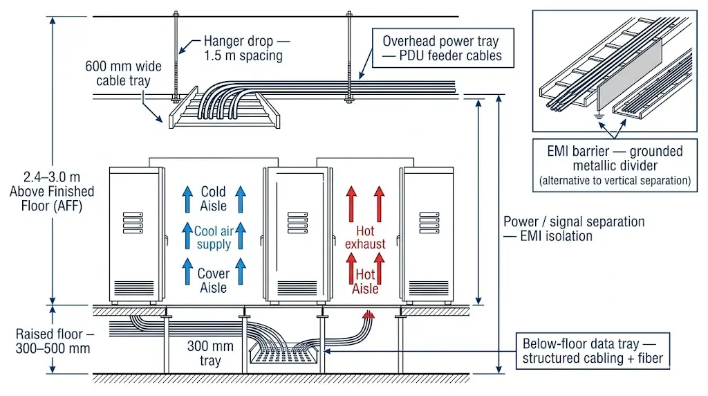
Figure 3. Two-layer cable tray architecture in a data center hot-aisle/cold-aisle configuration: 600 mm ladder tray at 2.4–3.0 m AFF carries PDU feeder cables overhead; perforated tray in the 300–500 mm raised-floor void routes structured cabling and fiber, with vertical separation between layers providing EMI isolation between power and signal circuits.
Maintenance Access and Inspection in Cable Tray Systems
One of the clearest field advantages cable tray systems hold over enclosed conduit is the ability to inspect, modify, and expand cable routing without dismantling the infrastructure. In the Suzhou pharmaceutical manufacturing upgrade (2023), maintenance crews accessed and rerouted 14 power and control cables within a single 8-hour shutdown window — a task that would have required 3 days of conduit removal under the previous enclosed raceway system.
Physical Access Requirements
Open-top ladder and ventilated trough trays allow technicians to visually inspect cable insulation, check for heat damage, and identify overloaded fills without removing covers. NEMA VE 1 recommends a minimum vertical clearance of 300 mm above the tray top rail for unrestricted hand access during cable insertion and repositioning. Installations in ceiling plenums often reduce this to 150 mm, which limits maintenance efficiency and should be documented in as-built drawings.
Walkable cable tray systems — rated for occasional foot traffic up to 150 kg/m² — are used in accessible floor plenums and raised-floor data centers where technicians may need to step across or alongside the tray runs. These require heavier gauge side rails (typically 2.5 mm steel minimum) and support spacing no greater than 1.5 m between hangers.
Inspection Intervals and Fill Monitoring
IEC 61537 does not prescribe maintenance intervals directly, but facility managers typically schedule visual inspections every 12 months in industrial environments and every 24 months in commercial buildings with stable thermal loads. The practical trigger for corrective action is cable fill ratio: when actual cable cross-sectional area exceeds 40% of the tray’s usable fill area, heat dissipation becomes restricted and ampacity must be recalculated per the applicable wiring standard.
Infrared thermography has become a standard inspection tool for cable trays carrying high-current power cables. A thermal scan identifying localized hotspots more than 15 °C above ambient on a cable bundle typically signals either excessive fill or a damaged cable requiring immediate investigation.
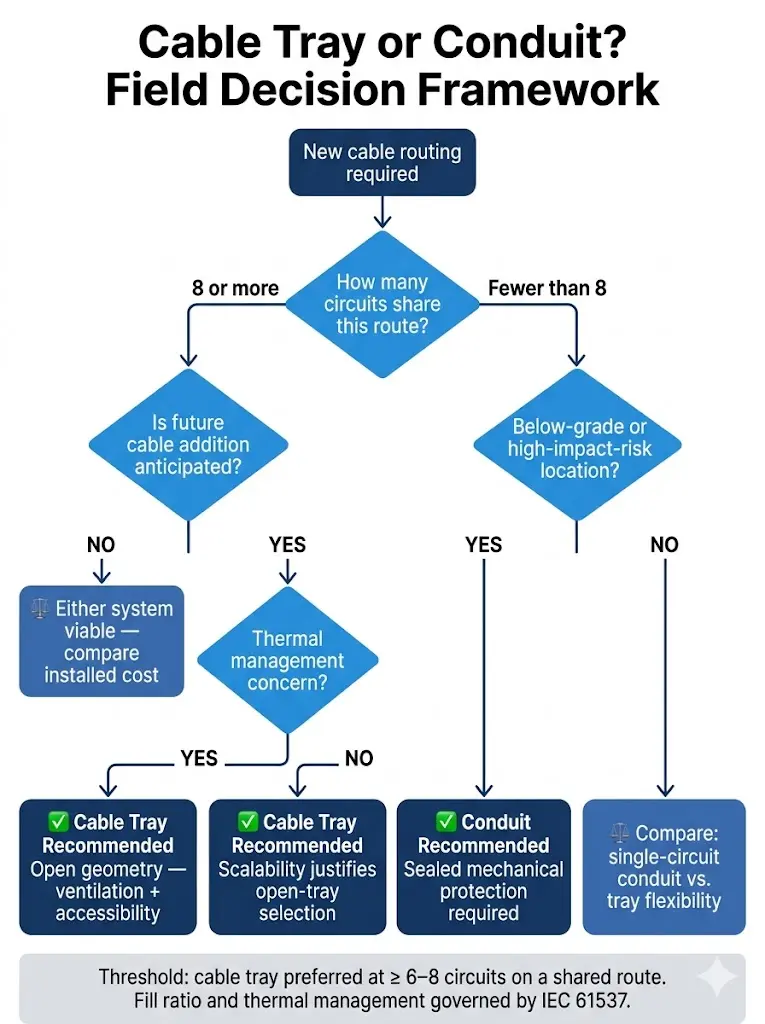
Figure 4. Field-based decision framework for cable tray versus conduit selection: the primary branch point is circuit count on a shared route — tray is the preferred system at eight or more circuits, where fill-ratio management, thermal dissipation, and future cable addition justify the open-structure approach over sealed conduit.
Selecting the Right Cable Tray System for Your Application
Choosing the correct cable tray requires matching structural type, material, and load class to the specific field conditions of the installation. A mismatch between tray selection and actual operating environment is one of the most common causes of premature failure, code non-compliance, and costly rework.
Assess the Mechanical Load Requirement
Start by calculating the anticipated cable load per unit length. Under IEC 61537, load classes range from Class A (50 kg/m) to Class D (200 kg/m). A ladder cable tray spanning 1.5 m between supports with a 120 kg/m cable fill sits squarely in the Class C range and requires a tray with a proof load rating of at least 150 kg/m to satisfy the 1.25 safety margin typically applied in industrial cable routing design. Undersizing at this stage leads to midspan deflection exceeding L/200, which strains cable jackets and creates long-term insulation damage.
Match Material to Environmental Exposure
Material selection is driven by chemical exposure, humidity, and temperature:
Hot-dip galvanized steel suits general industrial and outdoor environments where mechanical strength is the priority. ISO 1461 specifies zinc coating thickness at 45–85 µm, providing 15–25 years of corrosion resistance in C2–C3 atmospheric categories.
Stainless steel (Grade 316L) is required in coastal facilities, chemical plants, and food processing areas where chloride concentrations exceed approximately 200 ppm or where regular wash-down with acidic cleaners occurs. The molybdenum content ≥ 2.0% in 316L resists pitting in C4–C5 atmospheric categories per ISO 9223.
Fiberglass-reinforced plastic (FRP) is the preferred choice in strongly corrosive zones — wastewater treatment plants, battery rooms, acid-wash areas — where ambient pH routinely falls below 4 or rises above 10.
Verify Fill Ratio Before Finalizing Width
Cable fill ratio — the ratio of total cable cross-sectional area to usable tray interior area — directly affects ampacity derating. NEMA VE 1 recommends a maximum fill ratio of 50% for power cables in ventilated ladder trays and 40% for solid-bottom trays where heat dissipation is reduced.
A 300 mm wide ladder tray with 100 mm usable fill depth provides approximately 30,000 mm² of cross-sectional area. At the 50% fill limit, only 15,000 mm² is available for cable placement. That figure must be calculated before purchase, not discovered after installation.
For outdoor cable routing on rooftops or between buildings, UV-stabilized FRP or hot-dip galvanized steel trays with a minimum zinc coating of 85 µm are standard. Expansion splice plates are required at intervals not exceeding 15 m to accommodate thermal movement in exposed installations.
Start Specifying Your Cable Tray System
Before requesting a quote or submitting a design package, confirm two parameters: your maximum distributed cable load in kg/m and your environmental exposure category (indoor dry, outdoor UV-exposed, corrosive atmosphere, or wash-down). A ladder tray rated at 150 kg/m under IEC 61537 Class C in a galvanized finish will perform very differently over a 20-year service life in a coastal marine environment — where a 316L stainless steel or GRP system is the appropriate specification.
Cable tray systems span dozens of configurations — ladder, perforated, solid-bottom, wire mesh — and the correct choice depends on ventilation requirements, cable fill ratio targets, and seismic zone classification under applicable structural codes. An experienced supplier can cross-reference your conduit layout drawings against standard span tables and recommend support intervals that keep midspan deflection within acceptable limits.
In the 2023 pharmaceutical manufacturing expansion in Suzhou, early supplier engagement during schematic design reduced cable management rework during commissioning by over 40% and trimmed material procurement costs by approximately ¥280,000 compared to the originally specified conduit-heavy layout.
Reach out to our cable tray engineering team with your project drawings, cable schedule, and site environment classification for load calculations, material recommendations, and a compliant bill of materials tailored to your application. You can also explore our ladder cable tray series, review perforated tray options for data center deployments, and reference our technical guide on IEC 61537 load class selection for deeper specification support.
How this page differs from related XMQJ guides
This page focuses on its stated search intent. For product-level selection, start from Xinma Cable Tray Systems and then compare the related engineering guides linked above.
Engineering Evidence and Verification Sources
This article has been updated with explicit source and procurement checks so engineering, EPC, and purchasing teams can verify the recommendations instead of relying only on generic product descriptions. For project use, treat the table below as a starting evidence map and confirm the final requirements against local codes, consultant drawings, and supplier submittals.
Use this source to verify standards, product scope, installation assumptions, or supplier evidence before final specification.
Buyer Verification Checklist
Request drawings that show tray width, depth, side rail profile, bend radius, fittings, and support spacing.
Ask for load tables or engineering assumptions that state test span, load class, and deflection criteria.
Confirm material grade, surface finish, coating method, and corrosion exposure assumptions before comparing prices.
Check whether accessories such as covers, couplers, reducers, clamps, grounding jumpers, and brackets are included.
For EPC or export orders, review packaging, labeling, inspection records, and drawing revision control before shipment.
Frequently Asked Questions
How do I calculate the correct load class for a cable tray installation?
Add up the total mass of cables per linear meter of tray run — including all cables planned for future additions — then apply a 1.25 safety factor and select the IEC 61537 class that covers the result. A calculated load of 120 kg/m with the safety factor applied points to a Class C tray rated at 150 kg/m minimum.
What is the maximum cable fill ratio allowed in a ladder cable tray?
NEMA VE 1 recommends a maximum fill ratio of 50% for power cables in ventilated ladder trays, measured as total cable cross-sectional area divided by the usable tray interior area. Staying within this limit preserves ampacity ratings and leaves practical room for future cable additions.
When should fiberglass (FRP) cable trays be used instead of steel?
FRP cable trays are typically selected when the installation environment involves sustained chemical exposure that would degrade steel — such as wastewater treatment clarifiers, battery rooms, or acid-wash process areas where ambient pH falls below 4 or rises above 10 regularly.
How far apart should cable tray support hangers be spaced?
Support spacing depends on the tray’s span rating under its specified load class, but most ladder and perforated trays in industrial applications are installed on 1.5 m to 3 m centers. Vertical riser applications generally require supports at no more than 1.5 m intervals to prevent cable slippage under self-weight.
How does cable tray separation distance reduce electromagnetic interference?
Routing power cables and instrumentation or data cables in physically separate trays — with at least 200–300 mm of clearance between them — reduces magnetic field coupling between the high-voltage runs and the low-voltage signal wiring. Solid-bottom trays with metallic dividers provide additional shielding when parallel routing at closer spacing is unavoidable.
What are the main differences between ladder tray, perforated tray, and solid-bottom tray?
Ladder tray offers the best ventilation and easiest cable access, making it the standard choice for heavy power cables in industrial environments. Perforated tray provides moderate ventilation with a closed bottom that prevents debris from falling, well-suited to data center raised floors. Solid-bottom tray offers the greatest EMI shielding and is selected in plenum ceiling spaces and environments where cable protection from dripping liquids is required.
How often should cable trays be visually inspected in an industrial facility?
Inspection frequency depends on the facility type and thermal environment, but annual visual inspections are common practice in industrial settings with variable loads or chemical exposure. The practical trigger for immediate corrective action is a cable fill ratio above 40% of usable tray area, or a thermal scan showing hotspots more than 15 °C above ambient on a cable bundle.
Kevin Zheng
Kevin Zheng is a manager linked to Shanghai Xinma Busway & Cable Tray Co., Ltd. He writes technical content on cable tray systems, installation practice, sizing logic, load classes, and related standards for industrial and infrastructure applications.