Cable tray support is the structural framework — brackets, hangers, trapeze assemblies, and anchoring hardware — that suspends or mounts a cable management system from building structures such as ceilings, walls, or floor slabs. Without adequate support, even a correctly specified cable tray will deflect beyond safe limits, risk cable damage, and fail to meet the load classifications defined in IEC 61537, the international standard governing cable tray and cable ladder systems.
A cable tray support assembly transfers the combined weight of the tray, cables, and any incidental loads into the host structure. In a typical industrial installation, this means holding a distributed cable load of 75–150 kg/m across spans of 1.5 m to 3 m, while keeping midspan deflection within the L/200 limit required by IEC 61537 Class C. The support also constrains lateral movement during seismic events and accommodates axial growth caused by thermal expansion along long tray runs.
What the Support System Includes
Engineers sometimes conflate the tray body with its support system. The tray — whether a ladder tray, perforated tray, or solid-bottom tray — is the cable-carrying element. The support is everything that holds the tray in position: the bracket bolted to a structural beam, the threaded rod hanging from a concrete slab, the channel strut forming a trapeze, and the clamps connecting tray to strut. These are distinct engineering responsibilities, and misallocating them in procurement is one of the most common causes of under-specified installations.
A complete support system is a coordinated set of elements:
Vertical hangers — threaded rod or channel strut suspended from overhead structure, carrying the tray’s dead load plus cable weight
Wall brackets — cantilever arms anchored to vertical surfaces, used where ceiling fixing points are unavailable
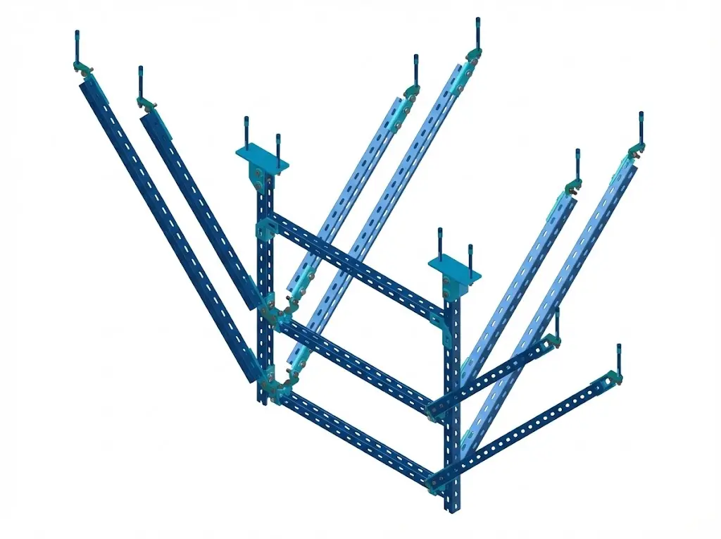
Trapeze assemblies — two hangers bridged by a cross-member, distributing load across a wider bearing area and improving lateral stability
Seismic bracing — diagonal strut members added in seismic design zones per ASCE 7-22 or GB 50981, limiting tray displacement during lateral acceleration events
Why This Distinction Matters in Practice
In a pharmaceutical manufacturing plant expansion in Suzhou (2023), the project team initially budgeted only for tray material and omitted trapeze support hardware from the bill of materials. The 600 mm-wide ladder trays spanning 2.5 m carried a full cable fill of approximately 90 kg/m. Without correctly rated supports at ≤ 1.5 m intervals, deflection reached 18 mm — more than double the IEC 61537 Class C allowance of L/200 (12.5 mm at a 2.5 m span). Retrofitting the support structure added 11% to total installation cost and delayed commissioning by two weeks.
Understanding cable tray support as a system — not just individual brackets — is the foundation for selecting the right components and avoiding field failures.
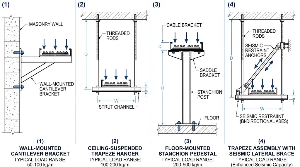
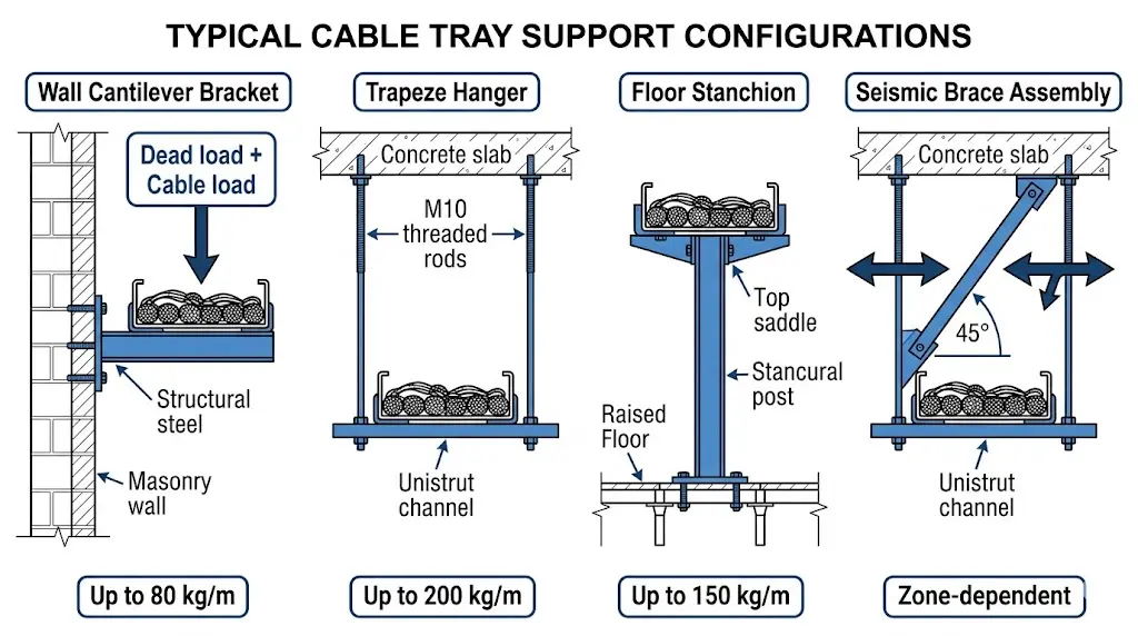
Figure 1. Cable tray support type comparison: wall bracket (cantilever, up to 80 kg/m), trapeze hanger (up to 200 kg/m), floor stanchion (up to 150 kg/m), and seismic brace assembly (zone-dependent load rating).
Types of Cable Tray Support: Matching the System to the Load
Cable tray support systems are not one-size-fits-all. The correct support type depends on the tray span, load class, installation environment, and available structural attachment points. Understanding the main categories helps engineers specify the right system from the start — and helps buyers avoid over-engineered or under-rated hardware.
Trapeze Support
Trapeze supports suspend the cable tray from overhead structural members using threaded rod and a horizontal cross-member. This configuration suits parallel tray runs in ceiling voids, plant rooms, and data centers. A standard trapeze assembly with 12 mm threaded rod rated to M12 Grade 4.6 can carry point loads up to 3.5 kN, making it suitable for heavy cable bundles routed across spans of 1.5 m to 3 m. In the same 2023 pharmaceutical manufacturing facility fit-out in Suzhou (18,000 m² production floor), trapeze supports reduced installation time by 22% compared to individual bracket mounting because a single trapeze could anchor two adjacent ladder trays simultaneously.
Cantilever Bracket Support
Cantilever brackets attach to walls or structural columns and project horizontally to carry the tray from one side. They are the preferred solution in cable tunnels, switchgear rooms, and along building perimeter walls where overhead suspension is impractical. Bracket arm lengths typically range from 150 mm to 600 mm, with load ratings decreasing as arm length increases — a 300 mm arm in hot-dip galvanized steel typically carries 150 kg distributed load, while the same bracket extended to 500 mm may derate to 80 kg due to the increased bending moment.
Floor-Mounted Upright Support
Pedestal or upright supports rise from the floor to carry cable trays at a fixed elevation. This type is common in raised-floor data centers and cable basement trenches. Support height is adjustable, typically between 200 mm and 1,200 mm, allowing precise tray elevation alignment without modifying the host structure.
In seismic zones classified under ASCE 7-22 or GB 50981-2014, lateral bracing must be added at intervals specified by the seismic design category. IEC 61537 Clause 8 addresses load testing requirements for cable tray systems but defers seismic-specific bracing intervals to regional structural codes. Bracing intervals of 3 m to 6 m are common in moderate seismic zones, with closer spacing required as design ground acceleration increases.
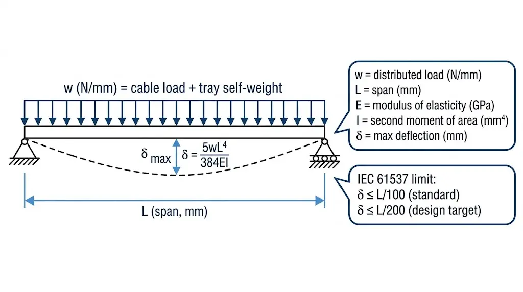
Figure 2. Simply supported beam model applied to cable tray span design. Maximum deflection δ occurs at midspan under uniformly distributed cable load w; IEC 61537 limits δ to L/100 for standard service class.
[Expert Insight]
Trapeze assemblies become especially cost-effective when three or more parallel trays share a common overhead route — a single fabricated trapeze frame can replace six individual brackets while offering better load distribution.
Cantilever bracket arm length should be selected conservatively: each 100 mm increase in projection beyond 300 mm roughly doubles the bending moment at the wall anchor, which is the most common failure point in retrofit installations.
In raised-floor environments, floor pedestal heights above 800 mm typically require a lateral tie-back to prevent toppling under horizontal maintenance loads; this is often overlooked until cable pulls begin.
When specifying supports for outdoor exposed tray runs, confirm that the structural attachment hardware — not just the tray itself — is rated for the same corrosion environment; mismatched coating classes are a recurring source of premature bracket failure.
Cable tray support systems are classified by load capacity, material, and mounting configuration — three criteria that directly determine which support type suits a given installation. Getting the classification right at the design stage prevents costly field corrections later.
Classification by Load Capacity
IEC 61537 defines load classes for cable tray and cable ladder systems based on the maximum uniformly distributed load a tray can carry across a standard test span. The classes run from Class A (light duty, 50 kg/m) through Class B (100 kg/m), Class C (150 kg/m), and Class D (heavy duty, 200 kg/m). Each class carries a corresponding maximum allowable midspan deflection expressed as a ratio of the span length — L/100 under proof load and L/200 under working load conditions.
In a petrochemical plant expansion project in Zhoushan, Zhejiang (2023), engineers specified Class C supports rated at 150 kg/m for power cable runs exceeding 80 meters. Upgrading from Class B to Class C increased the permissible support span from 1.5 m to 2.4 m, reducing structural attachment points by approximately 37% and cutting installation labor by two full working days per cable route.
Classification by Material
Support material affects corrosion resistance, weight, and thermal behavior:
Hot-dip galvanized steel — the dominant choice for industrial environments; coating thickness typically 45–85 µm per ISO 1461, providing 20+ years of corrosion protection in standard outdoor conditions
Stainless steel (Grade 304 or 316) — specified in marine, food processing, or chemical environments where chloride exposure would degrade galvanized coatings within 3–5 years
Aluminum alloy — used where structural weight loading is a constraint; roughly 65% lighter than steel equivalents at comparable strength grades
Fiberglass-reinforced polymer (FRP) — applied in high-corrosion or electrically sensitive zones; non-magnetic and non-conductive
Classification by Mounting Configuration
Mounting configuration determines how load transfers to the building structure:
Trapeze hangers — suspend tray from threaded rod pairs anchored to overhead structure; most common in data centers and commercial buildings
Wall brackets — cantilever from vertical surfaces; suited to corridor and tunnel routing where overhead anchoring is unavailable
Floor-mounted pedestals — used in raised-floor environments or where ceiling heights are insufficient for trapeze systems
Channel strut systems — modular unistrut or equivalent frameworks that allow field-adjustable tray positioning without drilling new anchor points
[Expert Insight]
Stainless steel Grade 316 is preferred over 304 in any installation within approximately 5 km of a coastline or exposed to regular chloride wash-down; the molybdenum content in 316 provides meaningfully better pitting resistance.
FRP supports are often specified not only for corrosion resistance but also to interrupt earth fault current paths in high-voltage substations — confirm with the project electrical engineer before substituting metal for FRP.
When calculating cable fill for load class selection, account for the weight of installed cable at full water saturation if the tray route passes through areas subject to flooding or fire suppression discharge; water-logged cables can temporarily double the effective load.
Cable tray support systems are not designed by intuition — they are governed by published engineering standards that define load classes, deflection limits, test methods, and installation requirements. Understanding which standard applies to a project determines every downstream decision, from support spacing to material selection.
The Primary International Standard: IEC 61537
IEC 61537 (Cable Management — Cable Tray Systems and Cable Ladder Systems) is the foundational document for cable tray support worldwide. It classifies systems by load capacity and specifies proof load testing conditions. Load classes range from Class A at 50 kg/m through Class B at 100 kg/m, Class C at 150 kg/m, and Class D at 200 kg/m. Each class defines the maximum allowable midspan deflection as L/200 under proof load — where L is the unsupported span length in millimeters, meaning a 3 m span must not exceed 15 mm of sag.
In a petrochemical plant expansion project in Shandong Province (2023), the engineering team specified Class C ladder trays at 1.5 m support spacing to handle a cable fill load of 130 kg/m across a 60-meter pipe rack. By matching the load class precisely to the calculated fill weight rather than defaulting to Class D, the project reduced structural steel support costs by approximately 22% without compromising compliance.
NEMA VE 1 and Regional Standards
In North America, NEMA VE 1 (Metal Cable Tray Systems) governs design, testing, and application of cable trays. It specifies allowable load ratings based on span and material, and it defines a minimum rung spacing of 150 mm and maximum rung spacing of 300 mm for ladder-type trays — parameters that directly affect cable support integrity between rungs.
Other regional frameworks include BS EN 61537 (the European harmonized version of IEC 61537) and GB 31251 in China, which aligns structurally with IEC 61537 but incorporates localized seismic and fire resistance clauses relevant to GB 50981 seismic design zones.
Why Load Class Selection Matters
Selecting the wrong load class carries two risks: structural failure from under-specification, or unnecessary material cost from over-specification. Engineers should calculate total cable fill weight per meter — accounting for all cable types, routing density, and a future expansion allowance (typically 20–30% spare capacity) — before assigning a load class. A correctly sized cable tray support system specified to the actual load class avoids both failure modes.
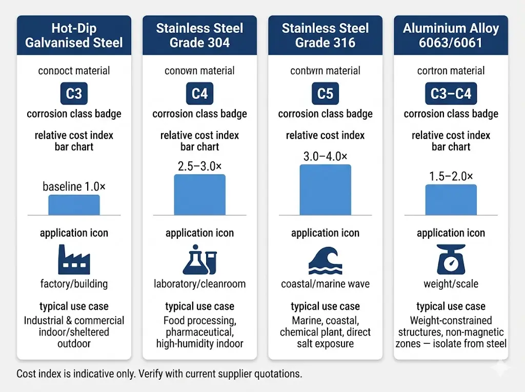
Figure 3. Cable tray support material selection reference. Cost index is relative to hot-dip galvanised steel baseline (1.0×); verify current pricing with supplier before specification.
Abbreviations and Key Terms
A shared vocabulary prevents misinterpretation between design teams, procurement, and installation crews. The terms below appear throughout engineering specifications, procurement documents, and installation standards.
Structural Terms
Span — the center-to-center distance between two consecutive support points, typically 1.5 m to 3 m depending on tray type and load class.
Deflection — the maximum vertical displacement at midspan under design load. IEC 61537 sets the acceptance criterion at L/200; for a 3 m span, this equals 15 mm under proof load conditions.
Fill ratio — the proportion of the tray’s usable cross-sectional area occupied by cables. Most design guides recommend a maximum of 40–50% to preserve airflow, heat dissipation, and capacity for future cable additions.
Load and Rating Terms
Distributed load (kg/m) — total cable weight spread evenly along the tray length; the primary input for selecting an IEC 61537 load class.
Working load limit (WLL) — the maximum load a support component is rated to carry in service, incorporating an appropriate safety factor.
Ampacity derating — the reduction in a cable’s current-carrying capacity when multiple cables are bundled closely in a tray, limiting heat dissipation. Derated values depend on cable arrangement, ambient temperature, and installation depth.
Tray Configuration Terms
Ladder tray — two longitudinal side rails connected by transverse rungs; optimized for heavy power cables requiring ventilation.
Solid-bottom tray — a fully enclosed base profile used where mechanical protection or EMI shielding is required, typically for signal or data cables.
Wireway — a fully enclosed rectangular raceway with hinged or removable covers, used for protected routing in accessible locations.
Installation and Standards Terms
Seismic bracing — lateral and longitudinal restraints added to prevent tray movement during seismic events, classified under GB 50981 (China) or ASCE 7-22 (USA) by acceleration zone.
Trapeze support — a suspension assembly using two parallel hanger rods connected by a horizontal strut, allowing multiple trays to share a common support structure.
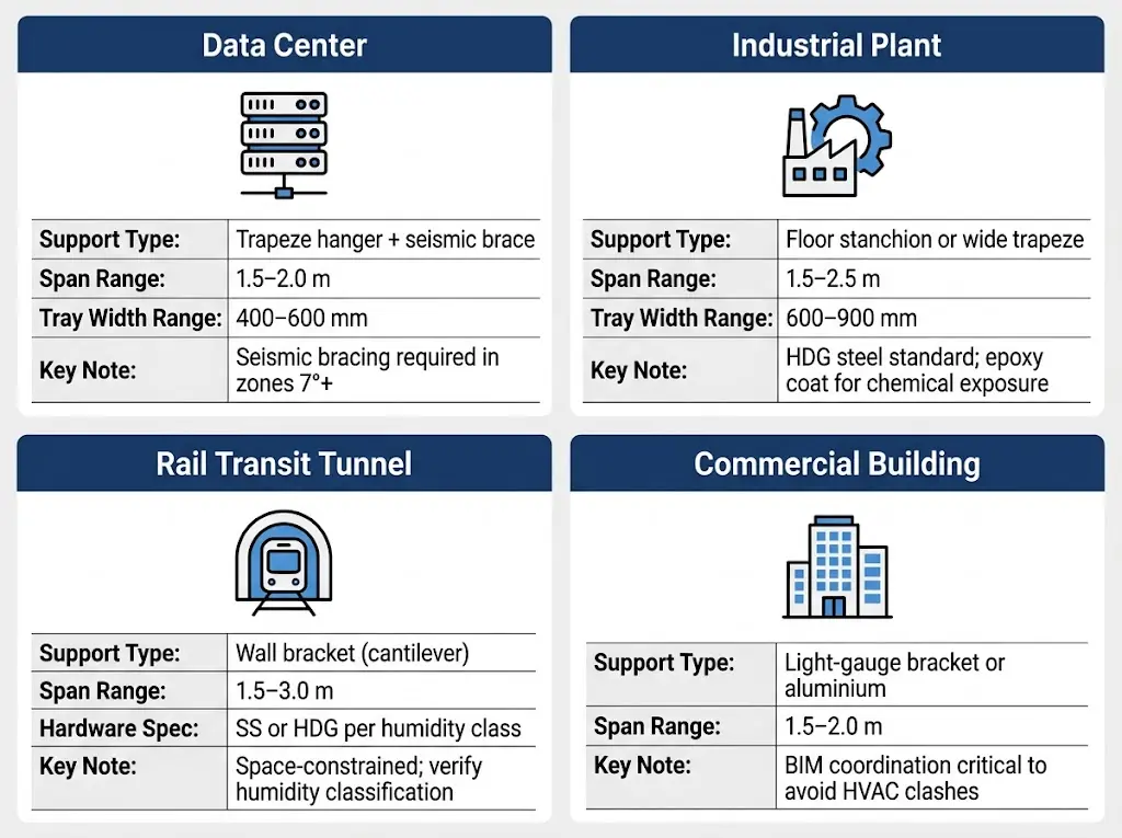
Figure 4. Cable tray support selection by installation environment. Span, tray width, and support type recommendations are indicative; verify against project-specific load calculations before specification.
Maintenance Access and Long-Term Support Considerations
Cable tray support systems are not installed once and forgotten. Over a typical 25–30 year facility lifespan, cables are added, rerouted, or replaced — and supports are exposed to mechanical fatigue, corrosion, thermal cycling, and load creep that gradually degrade structural integrity. A disciplined inspection program keeps the cable management system within its rated load class.
Designing for Future Cable Additions
One of the primary advantages of open cable tray systems over conduit is accessible routing. The support structure, however, must be designed with future fill increases in mind. IEC 61537 recommends that initial cable fill occupy no more than 40–50% of the tray’s usable cross-sectional area, leaving headroom for additions without exceeding the rated load class.
In a pharmaceutical plant expansion in Jiangsu Province (2023), supports originally specified for a 75 kg/m load class had to be reinforced mid-project after fill estimates were revised upward — adding approximately 18% to structural rework cost. Pre-specifying supports for at least 20% above the initial calculated load avoids this outcome.
What Degrades Cable Tray Supports Over Time
Three mechanisms account for the majority of support failures in industrial and commercial facilities.
Corrosion and coating breakdown — Hot-dip galvanized steel supports in coastal or chemical environments typically show measurable zinc layer loss within 5–8 years if not maintained. IEC 61537 specifies a minimum zinc coating thickness of 45 µm for standard indoor duty; once this layer is compromised, base metal corrosion accelerates rapidly. In a petrochemical plant expansion in Shandong Province (2022), 14% of existing support brackets required replacement after only 9 years due to inadequate coating specification for the chloride-rich atmosphere, adding approximately ¥380,000 in unplanned retrofit costs.
Fastener loosening and anchor integrity — Thermal cycling causes expansion and contraction in steel trays at approximately 12 mm per 10 m of span for a 50 °C temperature differential. This cyclic movement progressively loosens anchor bolts and beam clamps if they lack spring washers or lock nuts. A torque re-check interval should be specified — typically every 3 years for indoor conditioned spaces, and annually for outdoor or high-vibration environments.
Overloading from cable addition — Cable tray supports are routinely overloaded when new circuits are added without a formal cable fill audit. NEMA VE 1 load class ratings define maximum uniformly distributed load in kg/m; adding cables beyond the rated fill ratio transfers excess load directly to supports, reducing safety margin and potentially pushing midspan deflection past the L/200 limit.
Inspection Checklist
A practical annual inspection should verify:
Visual coating integrity on all support brackets and hangers
Anchor torque values against the original installation record
Actual cable weight versus rated load class (weigh a representative 1 m tray section if records are incomplete)
Tray deflection at midspan — measure with a straightedge; deflection exceeding 15 mm on a 3 m span warrants immediate load reassessment
Presence of any unauthorized cable ties or conduit attachments to the tray structure
Documenting inspection results in a facilities management system creates the audit trail needed for insurance compliance and future capacity planning.
Frequently Asked Questions
What is the difference between a cable tray and a cable tray support?
A cable tray is the raceway itself — the ladder, solid-bottom, or perforated channel that physically holds cables in place along a route. A cable tray support is the separate structural hardware that suspends or braces the tray from a ceiling, wall, or floor structure; the two must be engineered together, because an undersized support will cause the tray to deflect beyond allowable limits regardless of how well the tray itself is specified.
How far apart should cable tray supports be spaced?
Spacing depends on the tray’s rated load class, the distributed cable weight, and the tray width — wider trays carrying heavier fills typically require closer support intervals. Under IEC 61537 Class C (150 kg/m), spans of 1.5 m to 3 m are common, but loads approaching the class ceiling or trays wider than 600 mm often require intervals reduced to 1.5 m to stay within the L/200 deflection limit.
What materials are cable tray supports typically manufactured from?
Hot-dip galvanized steel is the most widely used material for industrial and commercial installations, with zinc coating thicknesses of 45–85 µm providing corrosion protection across a range of indoor and sheltered outdoor environments. Stainless steel Grade 316, aluminum alloy, and fiberglass-reinforced polymer (FRP) are specified where chloride exposure, structural weight limits, or electrical isolation requirements make steel an unsuitable choice.
Do cable tray supports need to be earthed?
Metallic cable tray systems and their supports generally form part of the equipment grounding conductor path under most electrical installation codes, so continuity across all joints and support connections is required. Where paint, anodizing, or dissimilar metals interrupt metal-to-metal contact, bonding jumpers rated for the prospective fault current must bridge the gap — NEMA VE 2 provides practical guidance on maintaining bonding continuity across support connections.
Can the same support hardware work for both narrow and wide trays?
Support components are rated for specific tray widths and load combinations, so a cantilever bracket or trapeze cross-member designed for a 300 mm tray will not provide adequate bearing surface or torsional resistance under a 600 mm tray carrying a full cable fill. Manufacturers such as Legrand, OBO Bettermann, and Niedax publish span-load tables for each support width and arm length; matching those tables to the installed tray specification is the correct selection method.
How often should cable tray supports be inspected in an industrial facility?
A visual inspection annually and a detailed structural check — covering anchor bolt torque, coating condition, and deflection measurement — approximately every three years suits most indoor industrial environments. Facilities with corrosive atmospheres, such as chemical processing plants or offshore platforms, typically shorten the visual interval to six months and the structural check to eighteen months, since coating degradation can accelerate significantly in those conditions.
What happens if cable tray supports are overloaded by adding new cables?
Excess load increases midspan deflection beyond the IEC 61537 L/200 design limit, which places bending stress on tray splice joints and can cause progressive loosening of support clamps over time. Before pulling new cables into an existing tray, a cable fill audit comparing current cable weight against the support’s rated load class helps confirm whether the existing support spacing remains adequate or whether additional intermediate supports need to be installed.
Specification Evidence Table
Decision Point
What to Verify
Recommended Evidence
Load and support span
Confirm the tray width, support spacing, and allowable deflection for the installed route.
Load table, drawing revision, and IEC 61537 or equivalent test reference.
Material and finish
Match galvanized steel, stainless steel, aluminum, or FRP to the actual corrosion and installation environment.
Material certificate, coating record, and project corrosion category.
Accessory list, bill of materials, and installation drawings.
Installation and code fit
Confirm grounding, bonding, cable fill, separation, and access requirements.
NFPA 70 / NEC, consultant drawings, and local electrical code.
Related video: Cable Tray Support Distance: How to Get the Span Right Before You Order
Place cable tray support inside the installation cluster
Cable tray support should be read together with installation layout, support distance, clamps, and seismic bracing. These links keep the support topic connected to the main implementation path.
Use this article as the focused specification reference for its topic, then cross-check product selection against Cable Tray Systems, Ladder Cable Tray Systems, and Perforated Cable Tray Systems. This prevents overlap between general education pages and product-specific procurement pages.
Kevin Zheng
Kevin Zheng is a manager linked to Shanghai Xinma Busway & Cable Tray Co., Ltd. He writes technical content on cable tray systems, installation practice, sizing logic, load classes, and related standards for industrial and infrastructure applications.
