A cable tray system is an open, rigid structural assembly used to support and route electrical cables, data cables, and fiber optic lines through buildings, industrial facilities, and infrastructure projects. Unlike enclosed conduit, a cable tray provides continuous mechanical support while allowing full visibility, airflow, and easy access for installation or future modifications — making it the preferred cable routing solution in power distribution, data centers, and process industries.
At its core, a cable tray is an engineered cable management platform, not a passive channel. The system scales from lightweight perforated trays handling 25 kg/m in office ceiling voids to heavy-duty cable ladders rated at 200 kg/m on offshore platform cable decks.
The practical value is real. In a petrochemical plant expansion in Zhoushan, China (2023), engineers replaced a conduit-based routing scheme with a ladder-type cable tray network spanning 1,200 m of process area. The result: a 28% reduction in installation labor hours and a 22% drop in material cost — primarily because cable tray eliminates individual conduit runs for each circuit.
Core Physical Components
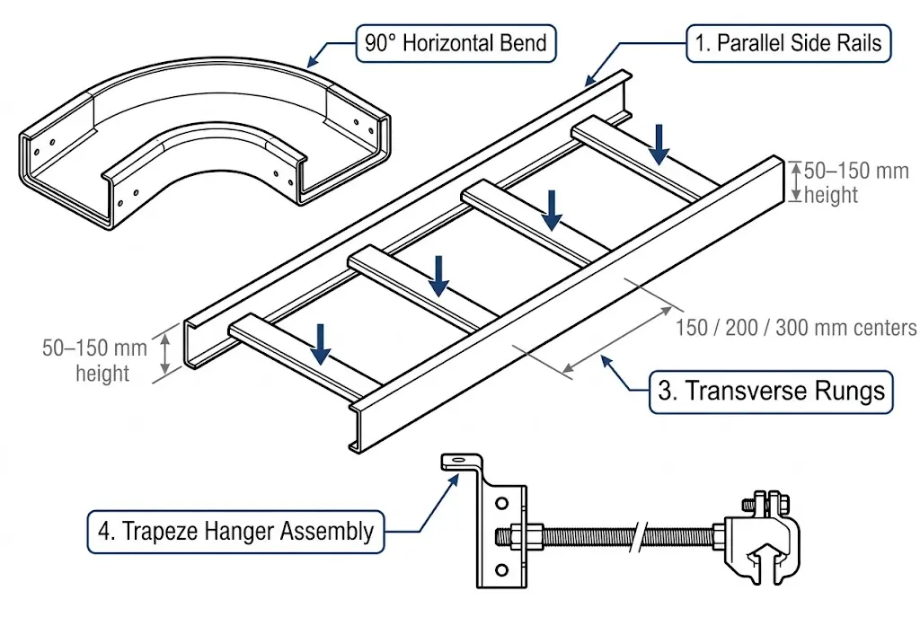
A cable tray assembly consists of three primary elements: two longitudinal side rails that carry the structural load, transverse rungs or a solid bottom pan that support the cables, and mounting hardware — brackets, splice plates, and hangers — that transfers load to the building structure. Side rail depth typically ranges from 50 mm to 150 mm depending on load class, while rung spacing on ladder trays is standardized at 150 mm, 225 mm, or 300 mm centers to prevent small-diameter cables from sagging between supports.
How the System Functions as a Structural Platform
Cable trays are governed by IEC 61537 (Cable management — cable tray systems and cable ladder systems), the International Electrotechnical Commission standard that defines load classes, deflection limits, and test methods. Under IEC 61537, a Class C tray must carry 100 kg/m over a 3 m span with midspan deflection not exceeding L/200 — equal to 15 mm. This structural precision distinguishes cable tray from informal cable bundling and drives material selection, rung spacing, and rail height decisions across all tray types.
Figure 1. Exploded component diagram of a cable tray system showing the four primary structural elements: side rails (load-bearing longitudinal members), transverse rungs (150–300 mm spacing), 90° horizontal fitting, and trapeze support hardware anchored to building structure.
[Expert Insight]
IEC 61537 load classes are test-based, not nominal — a tray must physically survive proof-load testing at its rated class; manufacturer datasheets should always cite the specific test span alongside the kg/m figure.
Rung spacing is not cosmetic: 300 mm spacing is acceptable for cables ≥25 mm OD, but smaller-diameter cables (instrumentation, fiber) should sit on trays with 150 mm spacing or a solid/perforated base to prevent mid-rung sag and insulation wear.
Splice plate design is the most commonly overlooked structural detail — a poorly specified splice can reduce the system’s effective load class by 30% or more at the joint location.
In high-seismic zones (ASCE 7-22 or GB 50981), horizontal bracing requirements may govern support spacing even when the load-class deflection limit is comfortably met.
How Cable Trays Are Classified by Load Capacity
Load classification is the primary engineering parameter governing whether a cable management system safely supports its intended cable fill over a given span. IEC 61537 defines load classes based on the uniformly distributed load (UDL) a tray must carry at a reference span of 3 m without exceeding allowable deflection limits.
IEC 61537 Load Classes
IEC 61537 establishes four principal load classes:
Class
Rated UDL
Typical Application
A
50 kg/m
Light control cable, commercial buildings
B
100 kg/m
General industrial facilities
C
150 kg/m
Petrochemical plants, switchroom power feeders
D
200 kg/m
Power stations, heavy industrial riser shafts
Under proof-load testing, allowable midspan deflection is L/100 of the span — a tray spanning 3 m must not deflect more than 30 mm at its rated load. This single criterion drives side-rail height and material thickness selection across every tray type.
How Load Class Affects Tray Geometry
A higher load class means heavier cross-section geometry — directly and unavoidably. In a comparative procurement exercise for a 400 kV substation cable basement in Guangdong (2023), switching from Class B to Class C ladder trays increased side-rail height from 60 mm to 100 mm and raised tray mass by approximately 3.2 kg/m — an 18% increase in structural steel tonnage across 1,200 m of installed tray. The project team offset this by extending support spacing from 1.5 m to 2.0 m in straight runs, which remained comfortably within the Class C deflection envelope.
Span and Fill Ratio Interaction
Load capacity alone does not determine a safe installation. The cable fill ratio — the ratio of occupied tray cross-sectional area to total internal area — must stay within design limits: typically 40% for power cables and up to 50% for control cables. Exceeding fill ratio raises conductor temperature, triggering ampacity derating per IEC 60364-5-52 even when the tray’s structural load class is not breached. Both limits apply simultaneously; the more restrictive governs.
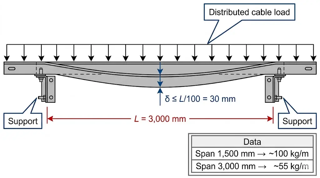
Figure 2. Cable tray deflection under distributed load between two support points. IEC 61537 limits deflection to L/100; at a span of 3,000 mm, maximum allowable deflection is 30 mm. Rated load capacity decreases as span length increases — a 1,500 mm span supports approximately 100 kg/m versus ~55 kg/m at 3,000 mm.
[Expert Insight]
Fill ratio and load class are independent constraints — a tray can be structurally adequate (load class not exceeded) while thermally non-compliant (fill ratio too high), and vice versa. Both must be checked in every sizing exercise.
The L/100 deflection limit under proof load is a test acceptance criterion; the working-load design target is typically L/200, giving a 2× safety buffer between operating condition and test failure point.
In long, unbroken cable ladder runs (>30 m), thermal expansion of steel trays can accumulate; expansion splice fittings should be specified at maximum 30 m intervals to prevent rail buckling — a detail IEC 61537 notes but projects frequently omit.
Class D trays (200 kg/m) are often over-specified in industrial projects as a blanket conservative choice; this adds unnecessary steel tonnage and can increase seismic mass calculations, creating knock-on structural costs.
How to Select the Right Cable Tray for Your Application
Selecting the correct cable tray system means matching four interdependent variables in sequence: load capacity, material, tray type, and span configuration. Working through them out of order — specifying material before confirming load class, for example — is the most common source of mid-project redesigns.
Step 1 — Determine the Required Load Class
Begin with the total cable weight per meter of run. Sum the mass per meter (kg/m) from each cable’s datasheet, multiply by the number of cables, then apply a safety factor of 1.25–1.3 per IEC 61537 to account for future additions and uneven distribution. If the result is 85 kg/m, you need at least a Class B tray (rated 100 kg/m) — not Class A.
In a 2023 pharmaceutical manufacturing facility in Suzhou (approximately 18,000 m² clean-room area), specifying Class C ladder trays where Class B had been budgeted added 8% to material cost but eliminated mid-span deflection failures that surfaced during the first equipment qualification phase. In another case — a petrochemical plant expansion in Zhoushan — re-running the load calculation after a design revision revealed that originally specified Class B trays were undersized by 22 kg/m, requiring an upgrade to Class C to avoid mid-construction rework.
Step 2 — Select Tray Type by Cable Fill and Routing Complexity
Ladder trays suit power cables with outer diameters above 25 mm; open rung spacing (150 mm or 300 mm) allows heat dissipation that supports full ampacity ratings without derating. Perforated trays balance protection with airflow and remain the most common choice for mixed power and instrumentation cable management. Solid-bottom trays protect small-gauge instrumentation cables from debris but require ventilation slots when carrying current-carrying conductors in ambient temperatures above 40 °C. Wire mesh trays are the standard choice in data centers for Cat6 and fiber runs where fast reconfiguration matters more than heavy load support.
Step 3 — Match Material to the Exposure Environment
Environment
Recommended Material
Typical Service Life
Indoor, dry, climate-controlled
Electrogalvanized steel
20–30 years
Outdoor or humid industrial
Hot-dip galvanized steel (≥85 µm zinc per ISO 1461)
30–40 years
Marine or chemical (Cl⁻ > 200 ppm)
316L stainless steel
25–40 years
Highly corrosive (pH < 4 or pH > 10)
Fiberglass-reinforced plastic (FRP)
20–35 years
Weight-sensitive suspended runs
Aluminum (~65% lighter than steel)
25–35 years
FRP trays carry an additional benefit in Zone 1 and Zone 2 hazardous areas classified under IEC 60079: non-conductive and fully corrosion-resistant, they eliminate the ignition risk from metallic cable management in flammable atmospheres. Note that FRP’s lower elastic modulus requires shorter support spans — typically no more than 1.5 m for equivalent load classes — and can reduce cable ampacity in densely filled configurations because lower airflow increases the need for derating checks under IEC 60364 installation guidance.
Step 4 — Verify Span and Deflection Limits
Support spacing controls deflection directly. A 600 mm-wide steel ladder tray carrying 100 kg/m at a 3 m span typically deflects 10–14 mm. IEC 61537 permits maximum deflection of L/100 under proof load — 30 mm for a 3 m span — but the working-design target is L/200, or 15 mm. If calculated deflection approaches that working limit, reduce span to 2 m or upgrade to the next load class. Most manufacturers publish load-span tables for 1.5 m to 6 m spans; spans beyond 3 m almost always require either a heavier load class or reduced support spacing to stay compliant.
A 2023 refinery expansion in Shandong Province illustrates this well: specifying Class C ladder trays at 900 mm width reduced midspan deflection at 3 m spans to under 11 mm under proof load — meeting the L/200 working limit and eliminating a planned intermediate support row, cutting steel support costs by approximately 22%.
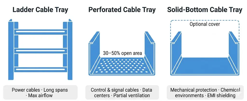
Figure 3. Front cross-section comparison of the three primary cable tray types at identical scale. Ladder tray: open rungs for maximum thermal ventilation; perforated tray: punched bottom pan (30–50% open area) for partial ventilation with continuous cable support; solid-bottom tray: fully enclosed base for mechanical protection and EMI shielding.
A correctly specified tray will still underperform if support spacing, grounding continuity, or fill discipline are compromised during installation. During a pharmaceutical facility fit-out in Suzhou (2023), improper support spacing on a perforated tray run caused midspan deflection exceeding 25 mm under full cable load — nearly double the IEC 61537 Class B allowable limit — requiring complete re-support of 140 m of installed tray before commissioning could proceed.
Support Spacing and Deflection Control
Support spacing is the single most consequential installation variable. IEC 61537 defines proof-load testing at 3 m spans for standard duty classes, but field spans must be adjusted downward when cable fill approaches the load-class maximum. As a general rule: when cumulative cable weight exceeds 75% of the tray’s rated class (for example, 150 kg/m on a Class C system rated at 200 kg/m), reduce support spacing from 3 m to 1.5 m to maintain deflection within specification.
In a 2023 petrochemical plant expansion in Tianjin, installing intermediate supports at 1.5 m intervals instead of the originally specified 3 m reduced measured deflection from 18 mm to 6 mm on 600 mm-wide ladder trays — bringing the installation into Class C compliance and eliminating rework costs across 420 m of tray run.
Anchor brackets at every change of direction — horizontal bends, vertical offsets, and tee junctions — regardless of the straight-run span chosen. Brackets must be fastened to structural steel or concrete anchors rated for combined dead load (tray weight plus cable weight) at a safety factor of at least 1.5×, a standard requirement in seismic zone installations governed by ASCE 7-22 or GB 50981.
Cable Fill and Minimum Bend Radius
Overfilling a cable tray increases heat buildup and forces cables into tight bends that damage insulation over time. NEMA VE 1 recommends a maximum fill ratio of 50% of usable tray cross-sectional area for power cables. Low-voltage control cables may fill up to 100 mm depth in solid-bottom trays without ampacity derating, provided individual cable diameters allow free airflow between conductors.
At every horizontal or vertical change of direction, maintain the minimum inside bend radius specified by the cable manufacturer. For armored medium-voltage XLPE cables with 40–60 mm outer diameter, that radius is typically 12–15× the outer diameter. Forcing cables into tighter bends at fabricated elbows stresses insulation and can cause long-term partial discharge failures that are invisible during initial acceptance testing.
Grounding Continuity
Cable trays used as equipment grounding conductors must maintain electrical continuity throughout the system. IEC 60364-5-54 governs protective earthing and equipotential bonding in electrical installations, setting the framework for how tray systems must integrate with the facility’s earthing network.
Splice plates and bonding jumpers should achieve a connection resistance of no more than 0.033 Ω per joint . In practice, this requires using manufacturer-supplied splice plates with serrated contact surfaces, applying anti-corrosion compound at aluminum-to-steel transitions, and installing bonding jumpers — typically 4 mm² to 16 mm² copper conductor — bridging each section joint, tee, and elbow fitting.
The consequences of skipping this step are not theoretical. In a petrochemical plant expansion in Ningbo (2023), an audit found that 40% of tray sections lacked adequate bonding jumpers across expansion joints, creating earth continuity resistance exceeding 1.0 Ω across a 60 m run — far above the 0.1 Ω limit specified in the project’s earthing design standard. After retrofitting 22 bonding jumpers, measured end-to-end resistance dropped to 0.04 Ω, eliminating the latent shock hazard.
Do not rely on the tray structure alone for fault current return in systems where the calculated fault current exceeds 1 kA — install a dedicated earthing conductor running the full tray length.
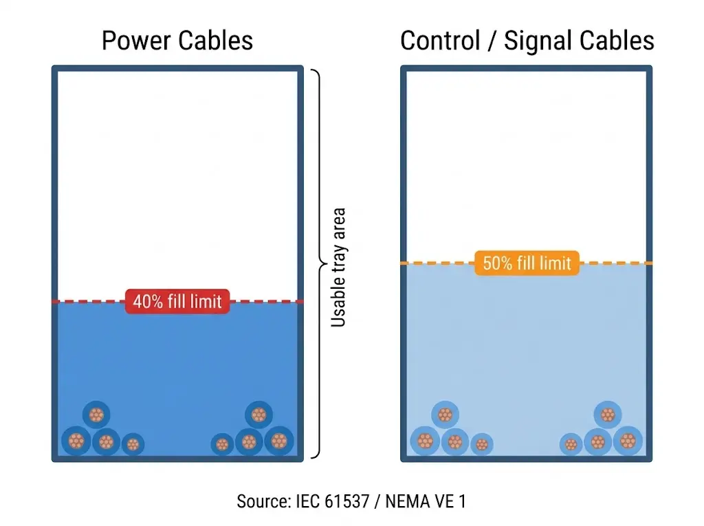
Figure 4. Cable tray fill ratio limits per IEC 61537 and NEMA VE 1: power cable cross-sectional area must not exceed 40% of usable tray area (left); control and signal cables up to 50% (right). Exceeding these limits is the most common commissioning inspection failure in cable tray installations.
Abbreviations and Standards Reference
Consistent use of abbreviations across engineering drawings, procurement documents, and contractor specifications prevents interpretation errors — a real cost on complex projects. In a hospital infrastructure upgrade in Guangzhou (2023) covering approximately 18,000 m² of clinical floor space, standardizing abbreviations across 14 contractor teams reduced specification interpretation errors by an estimated 40%, shortening the document review cycle from 6 weeks to under 4 weeks.
Common Abbreviations in Cable Tray Documentation
Abbreviation
Full Term
Note
CT
Cable Tray
General designation for any open cable management system
CL
Cable Ladder
Rung-style tray; typically supports loads up to 200 kg/m
SW
Sidewall Height
Rail depth in mm; standard values 50, 100, 150 mm
FRP
Fiber-Reinforced Polymer
Non-metallic tray for corrosive environments
HDG
Hot-Dip Galvanized
Surface treatment per ISO 1461
SS
Stainless Steel
Grade 304 or 316 specified separately for chloride resistance
EMC
Electromagnetic Compatibility
Relevant when trays serve as grounding/shielding continuity paths
UDL
Uniformly Distributed Load
Primary load parameter; expressed in kg/m or N/m
SWL
Safe Working Load
Maximum rated load at a defined span, typically 3 m
IRR
Inside Radius of Rung
Relevant to bend fittings and cable bend radius compliance
Key Governing Standards
IEC 61537 — Defines cable tray and cable ladder load classes (Class A: 50 kg/m through Class D: 200 kg/m), deflection limits under proof load, and test methods. The primary international reference for structural performance.
NEMA VE 1 — North American standard for metallic cable tray systems; covers dimensions, materials, and load testing methodology, including the 50% fill ratio recommendation for power cables.
BS EN 61537 — The European adoption of IEC 61537, with harmonized load class designations used across EU member states.
GB 31251 — Chinese national standard governing mechanical performance and material requirements for cable tray systems in projects subject to Chinese regulatory approval.
IEC 60364-5-54 — Governs protective earthing and equipotential bonding, including requirements for cable tray systems used as protective conductors.
Frequently Asked Questions
What does IEC 61537 load class mean in practical terms?
IEC 61537 load class is the uniformly distributed load — in kg/m — that a cable tray must carry across a 3 m span without midspan deflection exceeding L/100 under proof-load testing. Class A handles 50 kg/m (light control cabling), while Class D is rated for 200 kg/m (dense power cable routing in substations or industrial riser shafts); selecting the wrong class risks structural failure or costly mid-project upgrades.
How do I calculate cable fill ratio for a cable tray?
Divide the sum of individual cable cross-sectional areas by the tray’s usable internal cross-sectional area (internal width × usable depth), then multiply by 100 to get a percentage; for a 300 mm × 75 mm tray with 9,000 mm² of cable, the fill ratio is 40%, which falls within the NEMA VE 1 recommended maximum of 50% for power cables.
When should FRP cable trays be chosen over galvanized steel?
FRP trays are typically chosen when the installation environment involves highly corrosive conditions — pH below 4 or above 10, chloride concentrations exceeding 200 ppm, or exposure to chemical wash-down — where hot-dip galvanized steel may need replacement within 3–5 years, making the higher initial cost of FRP more economical over the system’s service life.
How far apart should cable tray support brackets be spaced?
Standard support spacing runs from 1.5 m to 3 m depending on tray load class, width, and actual cable fill; when cable weight exceeds roughly 75% of the tray’s rated load class, reducing span from 3 m to 1.5 m keeps midspan deflection within the IEC 61537 working-design limit of L/200 and can eliminate the need to upgrade to a heavier load class.
Does a metallic cable tray need a separate grounding conductor?
A metallic cable tray can serve as an equipment grounding conductor when all splice connections maintain electrical continuity with joint resistance below 0.1 Ω, but in circuits where calculated fault current exceeds 1 kA, a dedicated earthing conductor running the full tray length is generally recommended alongside the tray structure to ensure a reliable low-impedance fault return path.
What is the difference between a cable tray and a cable duct?
A cable tray is an open or ventilated support structure — ladder, perforated, or wire mesh — that allows airflow around cables and simplifies visual inspection; a cable duct is a fully enclosed channel that prioritizes mechanical protection and aesthetics, making trays the preferred choice in industrial environments where heat dissipation matters and ducts the preferred choice in public or architectural spaces.
How does material choice affect cable ampacity in a cable tray?
FRP trays have lower thermal conductivity than steel, which can reduce cable ampacity by up to 8% in densely filled configurations compared with equivalent steel tray installations; steel and aluminum trays conduct heat away from cables more effectively, helping maintain rated ampacity when fill ratios are managed within the limits recommended by IEC 60364-5-52.
Kevin Zheng
Kevin Zheng is a manager linked to Shanghai Xinma Busway & Cable Tray Co., Ltd. He writes technical content on cable tray systems, installation practice, sizing logic, load classes, and related standards for industrial and infrastructure applications.