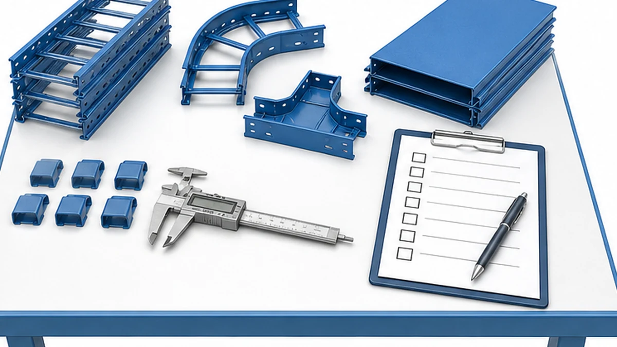
Industrial cable tray planning starts before a purchase order. EPC teams need a route that can be issued for construction, supplied as a complete bill of materials, installed in sequence, and inspected at handover. The usable planning record joins the cable schedule, route drawings, tray selection, fittings, support arrangement, finish, and delivery plan. Treating tray sections as a stand-alone commodity usually leaves the site team to solve interfaces after material arrives.
For an early system check, begin with the Xinma cable tray range. Confirm each route’s cable duty, environment, access constraints, and support concept before widths or quantities are released. This checklist is intended for EPC engineers, MEP contractors, procurement teams, and site inspectors. It does not replace the project electrical specification, approved load data, or the responsible engineer’s design.
1. Freeze the Planning Inputs Before Selecting Tray
Start from the latest controlled design information, not a previous project’s take-off. The minimum input set should include the cable schedule, route or model extract, electrical segregation requirements, environmental zoning, structural information, and the project delivery sequence. These documents establish what the route needs to do before a tray type is selected.
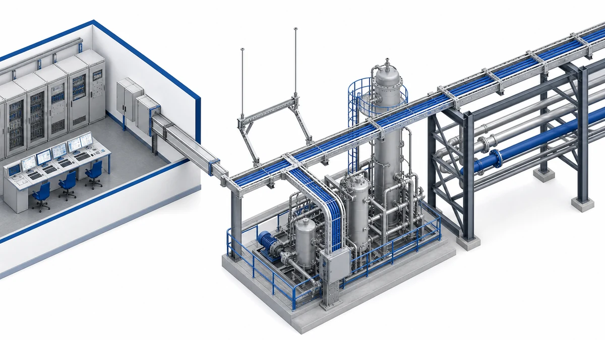
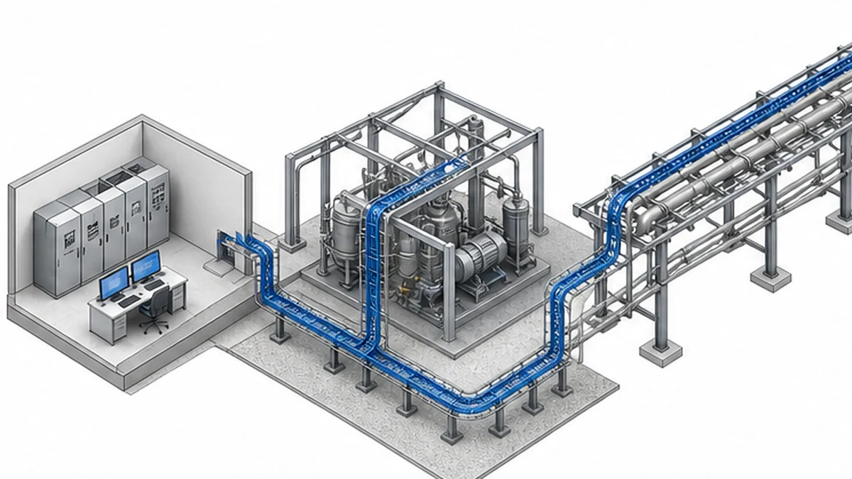
Split the project into practical zones. A dry control room, a process area, an outdoor pipe rack, and a coastal utility corridor can have different requirements for cable separation, corrosion protection, covers, access, and supports. Recording the zone against each tray run prevents one general material description from being copied into every line of the BOM.
Use the cable schedule to group cables by service and route segment. Include cable diameter, weight, quantity, entry and exit points, required separation, and any identified future allowance. The tray width is then checked against the approved calculation method and project specification. Do not select a width simply because the same nominal size was used on another site.
Zone-based planning starts with the controlled project inputs.
For open industrial power runs, a ladder cable tray system may be considered where the approved load data, cable support need, and maintenance access suit that configuration. Perforated and solid-bottom systems can be appropriate in other zones. The selection is a route-by-route engineering decision, not a site-wide default.
2. Turn the Route Into a Complete System BOM
An EPC tray BOM needs more than straight sections. Every change of direction, level, width, or support arrangement should be visible on the drawing and traceable to a line item. Ask the designer or detailer to resolve the following before procurement:
Straight lengths, widths, side-rail depth, material, finish, and section lengths.
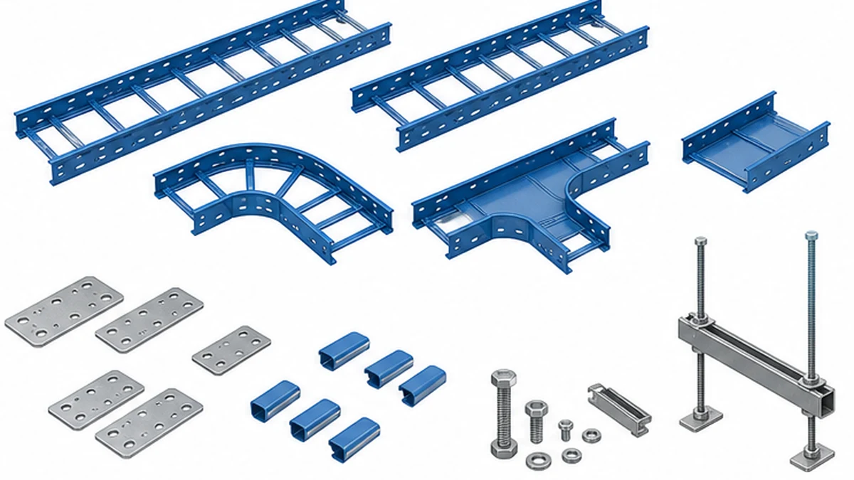
Horizontal and vertical bends, tees, crosses, reducers, and risers at the actual route locations.
Splice plates, fasteners, cover retention parts, dividers, clamps, and edge-protection items where the design needs them.
Trapeze frames, wall brackets, cantilevers, rods, anchors, and connection hardware for the support concept.
Any bonding, restraint, or labeling hardware required by the project documents.
The cable tray fittings catalogue is the compatibility cross-check for elbows, tees, reducers, risers, and splice hardware. A fitting should match the selected tray family and approved drawings. Hole patterns, rail geometry, width, finish, and grounding provisions can differ between systems, so substituting a visually similar fitting needs an engineering review.
In an anonymized 2024 pre-award review for an industrial process facility in eastern China, a roughly 480 m tray package was returned to engineering because the route model listed straight lengths but left several reducers and cover clips outside the purchase scope. The review closed the gaps before release and avoided a later site variation. The practical lesson was that a section count did not demonstrate an installable route.
A complete BOM includes more than straight tray sections.
3. Coordinate Supports, Interfaces, and Construction Sequence
Tray loading and supports must be planned together. The selected system’s published load data, support span, route geometry, cable weight, and structural anchors all belong in the design review. Direction changes, vertical transitions, and dense junctions can require separate support attention. The tray supplier cannot infer the final support design from a nominal tray width.
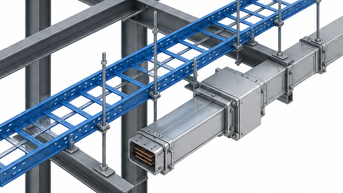
Use the existing cable tray support guide to structure the review around structure availability, support type, spacing shown on the approved design, and access for installation. On a shared steel frame, verify that busway hangers, process services, HVAC, and tray supports do not compete for the same anchor positions or maintenance clearance.
Where a route changes between busway-fed equipment and cable tray distribution, record the interface in the coordinated model or GA drawing. Confirm the equipment drop, cable entry direction, bracket locations, and whether a shared support structure is permitted. Where seismic restraint applies, retain the responsible engineer’s restraint design and make sure any braces, clamps, and anchors are included in the correct scope. These are project-specific decisions, not accessories to be added after dispatch.
Supports and system interfaces need coordination before release.
4. Specify Material, Finish, and Inspection Evidence by Zone
Finish and material should be assigned against the documented environment. The project corrosion strategy, area classification, temperature exposure, washdown conditions, and maintenance access provide the basis. Do not rely on an informal label such as “outdoor” or “industrial” as a complete material instruction.
The purchase specification should state what the site team will be able to verify at delivery. Typical evidence includes approved drawings, the supplier’s material declaration, finish information, dimensional records where required, packing lists, and lot identification. Where the contract calls for third-party inspection, define the hold points and acceptance documents before production begins.
At incoming inspection, compare the delivered tray with the approved order rather than judging it by appearance. Check width, rail depth, section length, material and finish identification, fitting orientation, splice-hole alignment, visible burrs, coating damage, and completeness of the supplied hardware. If cover clips, bonding components, or support items are packaged separately, verify them against the BOM before materials are distributed around the site.
In an anonymized 2023 data-room extension in Shanghai, a site receiving check on an approximately 60 m overhead route identified that the selected divider arrangement did not fit the corresponding fitting width. The mismatch was corrected before cable pulling. That check relied on a trial fit and the approved BOM, not an assumption that all parts with the same nominal width would connect.
Incoming inspection confirms that the package matches the approved BOM.
5. Keep the Handover Record Linked to the Installed Route
The final EPC check is documentation control. Mark up routing changes, record altered support locations, reconcile material lots, and retain inspection records with the handover package. Any construction change should be assessed for impact on fittings, supports, cable segregation, bonding arrangements, and the remaining material balance before it becomes an as-built condition.
Xinma manufactures cable tray sections alongside fittings, accessories, busway, and seismic-bracing components. For a coordinated supply package, the relevant product families can be checked for model-code consistency, finishes, support geometry, clamp or interface compatibility, BOM revisions, repeated deliveries, and inspection records. This supports operational coordination; final load, grounding, and restraint decisions remain with the responsible project team.
For the installation-stage sequence, refer to the cable tray installation guide. For the system-test context, use the current IEC 61537 publication. Neither source replaces the contract specification or local rules. Where acceptance depends on a particular load rating, span, grounding method, or test requirement, verify the approved manufacturer data and project documents.
EPC Release Checklist
Before issuing a tray purchase order, confirm that:
The latest cable schedule, route drawing, zone classification, and structural information are referenced.
Tray type, width, depth, material, and finish are assigned to each route segment through the approved design method.
Fittings, splice hardware, covers, dividers, supports, anchors, and required bonding or restraint parts are included in the BOM.
Tray, fittings, and accessories are matched to the selected product family and approved drawing interfaces.
Delivery lots follow the installation sequence, with an incoming-inspection plan and hold-point documents agreed before shipment.
Field changes are fed back into controlled drawings and handover records.
Frequently Asked Questions
What should an EPC team confirm before selecting cable tray width?
Confirm the current cable schedule, cable diameters and weights, segregation needs, route geometry, permitted fill method, future allowance, and the approved project calculation. Width should come from the documented design method, not a previous project’s nominal size.
Are fittings included automatically with cable tray straight sections?
Not necessarily. Elbows, tees, reducers, risers, splice plates, cover clips, and hardware should be explicit BOM items. Review the route drawing and supplier quotation together so every direction, level, and width change has a matched fitting and connection method.
How should cable tray supports be coordinated on an EPC project?
Review the selected tray’s published load data with the approved support design, structural anchors, route geometry, cable weight, and other services sharing the structure. The responsible engineer should approve support spacing and anchor details for the actual project conditions.
What should be checked when cable tray material arrives on site?
Compare dimensions, material and finish identification, fitting orientation, splice-hole alignment, hardware quantities, burrs, coating damage, and packing records with the approved drawings and BOM. Trial-fit representative sections and fittings before distributing a full delivery.
When should seismic bracing be included in a cable tray package?
Include it when the applicable project code and responsible engineer’s design require restraint for the route. Confirm the scope, component compatibility, anchors, and installation details before the purchase order. Do not add bracing as an assumed percentage of the tray quantity.
Kevin Zheng
Kevin Zheng is a manager linked to Shanghai Xinma Busway & Cable Tray Co., Ltd. He writes technical content on cable tray systems, installation practice, sizing logic, load classes, and related standards for industrial and infrastructure applications.