Heavy-Duty Cable Tray: Quick Definition and Core Criteria
A heavy-duty cable tray is a cable management system designed to carry high cable loads (typically ≥150–200 kg/m) over long spans (up to 3–6 m) with limited deflection and strong resistance to mechanical, thermal, and environmental stresses. It is specified when standard ladder or wire tray cannot meet required load and safety margins.
In practice, engineers move to heavy-duty tray when calculated cable mass plus future allowance exceeds the IEC 61537 or NEMA VE 1 load class of standard products, or when seismic, wind, or maintenance walk-on loads become governing. On industrial routes I’ve reviewed, re-checking load class against real cable schedules often changes tray series or support spacing.
Core Selection Criteria for Heavy-Duty Trays
Load Class and Deflection
Check rated uniformly distributed load (UDL), e.g., 200–300 kg/m at a defined span such as 2.5 m.
Deflection limit is usually L/200 or tighter; exceeding this can overstress cable sheaths and joints.
Span and Support Configuration
Longer spans (3–6 m) reduce support steel but require heavier side rails and rungs.
Shorter spans (1.5–2 m) can allow lighter tray series; trade-off is more supports and installation time.
Environmental and Corrosion Resistance
Outdoor petrochemical or coastal plants often require hot-dip galvanized ≥70 µm zinc or stainless steel for 15–25 year life.
Indoor heavy-duty runs may use pre-galvanized or painted steel if humidity and chemical exposure are low.
Cable Type and Fill Ratio
Power cables ≥1 kV and large cross-sections (e.g., 3×240 mm²) demand higher stiffness and wider rungs.
Keep working fill ≤60–70 % of tray area to allow future circuits and heat dissipation.
Dynamic, Seismic, and Maintenance Loads
In seismic zones, horizontal and vertical accelerations (0.2–0.4 g) can add 20–40 % effective load.
Where maintenance staff may step on the tray, verify any walk-on rating and use covers or dedicated walkways instead of relying on assumptions.
Design takeaway: “Heavy duty” is not just thicker steel; it is a quantified combination of load class, span, environment, and cable fill. Always size tray using real cable weights plus future margin, then confirm the chosen series meets both static and dynamic load requirements under the applicable standard.
Understanding Heavy-Duty Load Classes and Tray Types
Heavy-duty cable trays are classified by how much uniformly distributed load they can carry over a given span while keeping deflection within limits set by IEC 61537 or NEMA VE 1. For a specifier, this “load class + tray type” combination drives support spacing, tray width limits, and whether the system will survive real installation loads, not just catalog numbers.
How Load Classes Work in Practice
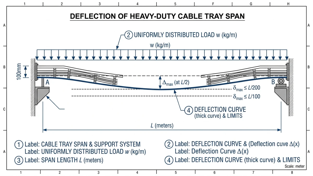
In IEC-style classification, typical heavy-duty ranges are around 150–300 kg/m UDL on a 2–3 m span, with maximum deflection often limited to L/200 or L/250. The physics is a simple beam problem: bending moment scales with span length squared (M ∝ L²), so doubling span from 2 m to 4 m roughly quadruples bending and deflection for the same load.
Design consequence: a tray rated 200 kg/m at 2 m span may only be acceptable for about 120–140 kg/m if you push the supports out to 3 m. When comparing products, always match:
Load class (kg/m)
Test span (m)
Deflection criterion (e.g., L/200)
If any of the three differ between suppliers, the “200 kg/m” numbers are not directly comparable.
Tray Types: Structural Behavior and Selection
The main heavy-duty tray types behave differently under load:
Cable ladder – Two side rails with rungs at 200–300 mm pitch. High bending stiffness, good for 300–600 mm widths and 3–6 m spans. Best where large power cables create ≥100 kg/m loads or where vertical drops and risers are common.
Solid-bottom tray – Continuous sheet with side rails. Good for small control cables and EMC; the sheet can govern stiffness. Often limited to 2–3 m spans for heavy loading unless thickness is increased.
Perforated tray – Compromise between ventilation and mass. Stiffness depends heavily on hole pattern and side rail profile; check load tables carefully for ≥400 mm width.
Wire mesh tray – Well suited for light to medium loads (e.g., <75–100 kg/m) and frequent re-routing, but usually not the first choice for heavy power feeders.
In deployments where tray width exceeds 600 mm and spans are ≥3 m, cable ladders with deeper side rails (e.g., 100–150 mm) consistently give better deflection performance and less vibration than perforated or wire mesh options.
A Simple Selection Scenario
If you expect 12 single-core 240 mm² power cables at 5.5 kg/m each, cable mass alone is about 66 kg/m. Add 20 % margin and a 10 kg/m allowance for future circuits and accessories, and you are near 90 kg/m design load. On a 3 m span, you should be looking at a ladder tray with a ≥150 kg/m load class at 3 m, not a lighter perforated tray whose 150 kg/m rating is only valid at 2 m.
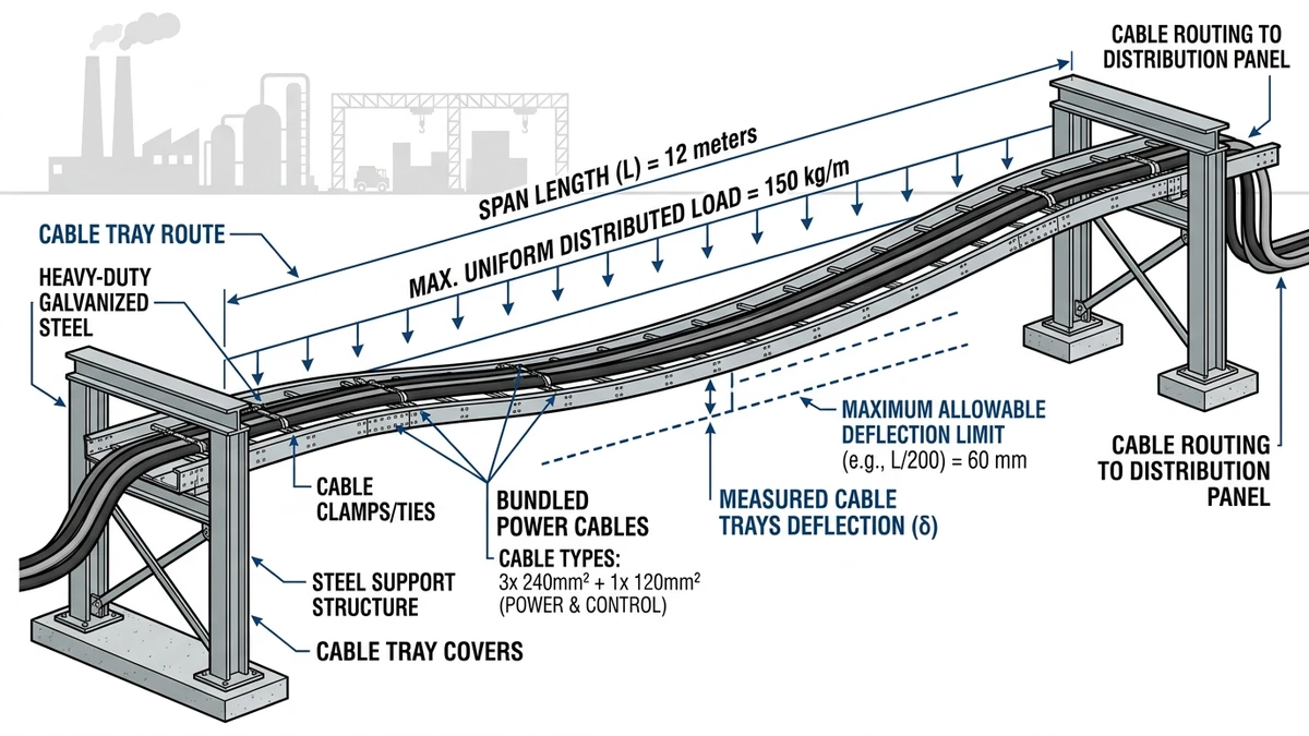
Figure 1. Structural schematic of a heavy-duty cable tray span indicating uniformly distributed load, span length, and maximum allowable deflection relative to span.
[Expert Insight]
– When you move from 2 m to 3 m spans, re-check not only tray load class but also splice plate strength; tests often show joints becoming the controlling element before rails.
– For multi-layer installations, some engineers specify the stiffest tray series on the top tier; this limits cumulative vertical deflection and keeps clearance to ceiling and pipework stable over time.
Where Heavy-Duty Cable Trays Are Used: Practical Scenarios and Risks
Heavy-duty cable trays are selected where cable weight exceeds roughly 50–75 kg/m, spans reach 3–6 m, or environmental and mechanical risks are high. In these settings, misclassifying load or environment is what typically causes cracking, excessive deflection, or corrosion in the first 3–5 years.
Field Application Matrix: Where Heavy-Duty Trays Make Sense
Scenario / Facility type
Typical conditions
Why heavy-duty tray is chosen
Key risks if you under-specify
Power plants & substations
11–220 kV circuits, 150–300 kg/m cable loads, 3 m spans
High load class, wide ladders, tight deflection limits
Sagging, cracked rungs, faulted power circuits
Petrochemical / refinery pipe-racks
Outdoor, corrosive, 4–6 m spans, 60–80 °C surfaces
Heavy-duty supports, clamps, often 316 SS or aluminum
Fatigue at fixings, dropped sections
How to Use This Matrix for Selection
Identify the governing stress: load (kg/m), span (m), or environment (corrosion, impact, fire).
Map your project to the closest scenario row.
If you hit two or more “Why heavy-duty” reasons in that row, treat heavy-duty tray as the default and check:
Load class vs. calculated cable mass (include 10–20 % spare capacity).
Support span vs. manufacturer rating (e.g., 4 m span may force a higher class).
Material and coating vs. environment (C3–C5 corrosion category, UV exposure).
On outdoor routes above traffic or carrying essential feeders, design teams frequently move one class up from the minimum that static load calculations suggest, to control deflection and reduce fatigue risk over a 25–30 year design life.
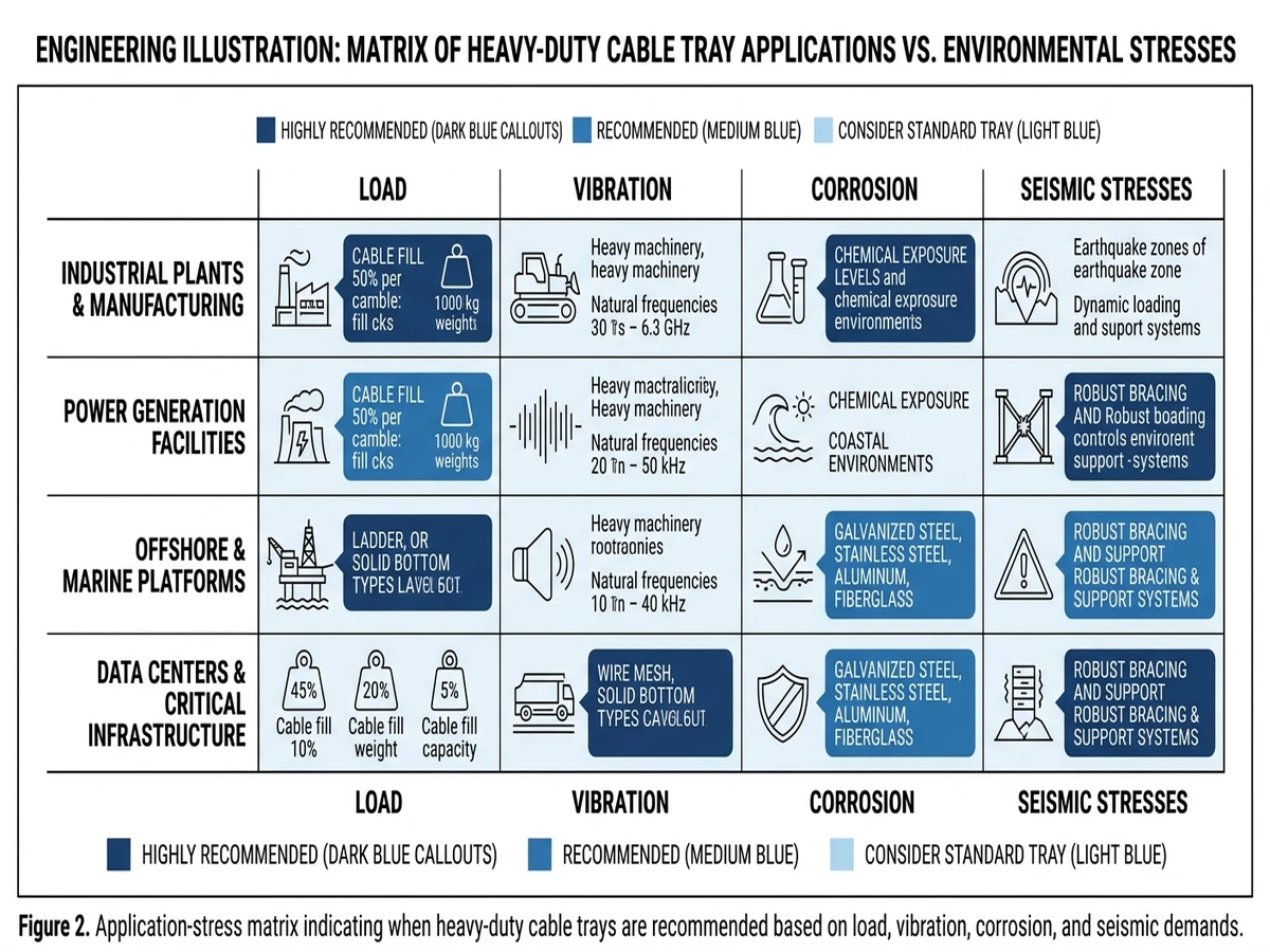
Figure 2. Application-stress matrix indicating when heavy-duty cable trays are recommended based on load, vibration, corrosion, and seismic demands.
[Expert Insight]
– In refinery pipe-racks we’ve reviewed, the worst damage rarely came from cable weight; it came from scaffold ties and small impacts that repeatedly bent under-sized trays near supports.
– Maintenance teams often report that misaligned supports at expansion joints become early crack points; aligning supports with fixed points during design tends to cut these issues significantly.
Buyer Checks: How to Specify the Right Heavy-Duty Cable Tray
Use this step-by-step checklist to move from “we need heavy-duty trays” to a defendable specification that will pass technical review and coordinate with other systems.
Step 1 – Define Route and Environment
Map each tray run: length, direction changes, and typical support span (e.g., 2.5–3.0 m between hangers indoors, often 1.5–2.0 m outdoors or in seismic zones).
Classify environment: indoor dry, corrosive industrial, coastal outdoor, high-dust, or high-temperature (>40 °C ambient).
Note special exposures: UV, chemical vapors, washdown, EMC-sensitive areas, or fire-rated escape routes.
Step 2 – Quantify Cable Load and Fill
List cable types, sizes, and mass per meter; calculate total distributed load in kg/m for each segment.
Apply a realistic fill ratio: for ladder or perforated tray, commonly ≤40–50 % of available area to allow future additions.
Add allowance for future circuits (typically 20–30 % extra load) and any point loads (e.g., 50–100 kg from junction boxes or transformers).
Step 3 – Select Load Class and Tray Type
Use your maximum calculated load and support span to select an IEC 61537 or NEMA VE 1 load class; for “heavy-duty,” this is often ≥150 kg/m at 2.0–3.0 m span.
Choose tray form (cable ladder, perforated tray, wire mesh) based on cable type, support requirements, and need for ventilation or frequent drop-outs.
Step 4 – Check Deflection and Support Strategy
Confirm midspan deflection limits (e.g., ≤L/200) under proof load from manufacturer data; tighten spans if deflection exceeds project criteria.
Verify that hangers, brackets, and building fixings are rated for combined dead load, live load, and seismic or wind actions.
Step 5 – Specify Material, Coating, and Grounding
Select material and finish (e.g., hot-dip galvanized steel ≥70 µm, stainless steel 304/316, or aluminum) according to corrosion class and mechanical needs.
Define bonding/earthing method: resistance per joint, bolted or clamped bonding jumpers, and continuity across expansion joints.
Step 6 – Address Covers, Fittings, and Accessories
Decide where covers are mandatory (outdoor, mechanical protection, EMC) and note their added mass in span calculations.
List required fittings: bends, tees, reducers, vertical risers, and transitions—specify radii consistent with minimum cable bending radius (e.g., ≥8× cable OD).
Include barriers, drop-out fittings, and splice plates; require all accessories to match tray material and finish.
Step 7 – Document Compliance and Installation Requirements
State applicable standards (e.g., IEC 61537 for cable tray systems, local fire and seismic codes).
Define installation constraints: maximum field cutting, support alignment tolerances, minimum clearances to other services, and inspection/maintenance access.
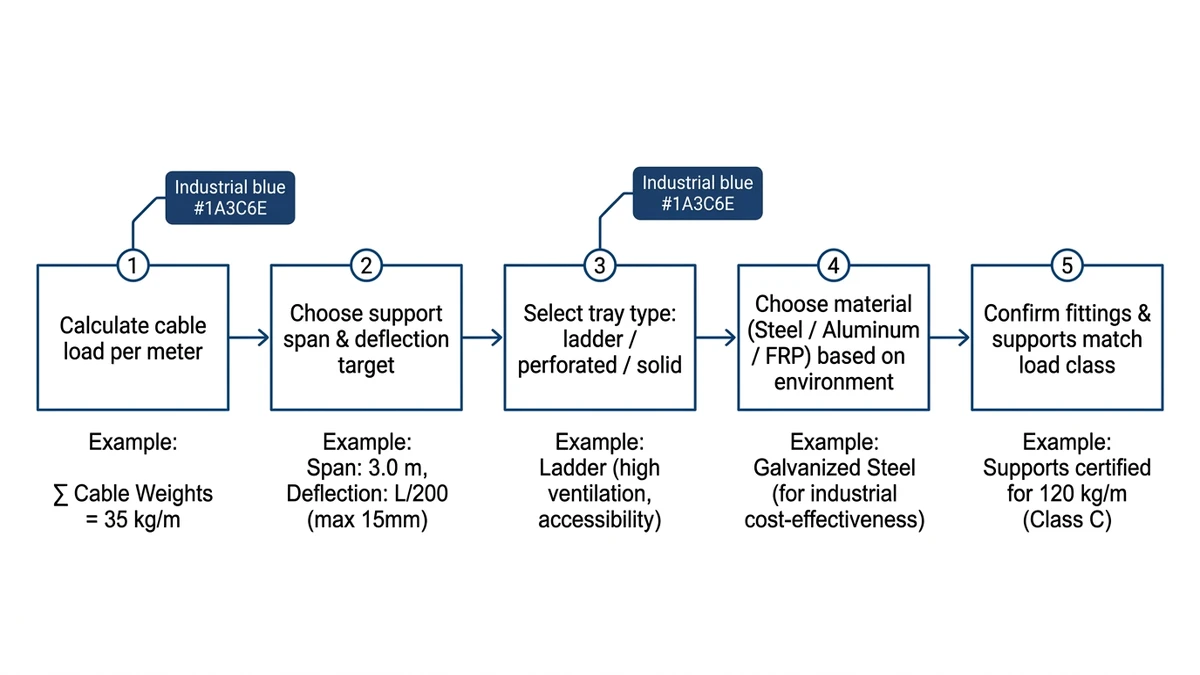
Figure 3. Selection flowchart guiding buyers through load calculation, span choice, tray type, material, and accessory coordination for heavy-duty systems.
Applying These Design Trade-Offs with Xinma’s Support
Across heavy-duty cable tray projects, the same design consequences keep recurring:
Higher load classes (e.g., 150–300 kg/m) drive either tighter support spans (often 1.5–2.0 m) or deeper, heavier side rails.
Outdoor or corrosive environments push you toward thicker zinc coatings or stainless steels, which increase self-weight by roughly 10–25 % and therefore hanger and anchor loads.
Covers and barriers add both mass and wind area, changing seismic loads and potentially requiring different bracing layouts.
High-current runs (800–2,000 A) need ampacity derating checks when trays are stacked, covered, or routed near heat sources.
These parameters interact. A change in tray width from 300 mm to 600 mm can invalidate a previous support layout; swapping from ladder to perforated tray changes thermal margins and allowable fill; adding 1.0 mm steel covers can move a system out of its original IEC 61537 load class if you do not re-check the structural tables.
In our heavy industrial deployments, the most robust designs came from treating the tray, supports, and building fixings as a single system and confirming:
Tray series vs. span vs. combined dead and live loads.
Support and seismic bracing capacity vs. increased self-weight and wind area.
Tray type and width vs. cable ampacity and routing constraints.
This is where Xinma’s engineering support is most useful: confirming load class versus span, validating fill and ampacity derating, checking fitting and support compatibility, and translating route drawings into a coherent tray specification (materials, finishes, covers, seismic details).
When you are ready, share your key parameters—span, environment, fault level, cable schedule—and Xinma can help you turn them into a coordinated heavy-duty cable tray bill of materials and outline installation notes, so your design is technically aligned before it reaches site.
For reference on how tray systems are tested and rated, you can review IEC’s cable management standard overview at: IEC 61537 publication page
To explore specific product ranges and coordinate them with your design:
For heavy-load ladder configurations, see the ladder cable tray range: ladder cable tray range
For general heavy-duty tray product options, including materials and finishes, review Xinma cable tray systems: Xinma cable tray systems
Where busway and heavy-duty trays interface on high-current routes, coordinate with busway system details: busway system details
How do I decide if my project really needs a heavy-duty cable tray?
Check the worst-case combination of cable load per meter, span, and environment; if loads exceed about 50–75 kg/m on spans ≥3 m or you have corrosive, outdoor, or high-impact conditions, moving to a heavy-duty class is usually safer than stretching a light-duty tray.
What is a reasonable safety margin when calculating cable loads for heavy-duty trays?
Engineers often size trays on calculated cable weight plus 20–30 % margin to cover future circuits, accessories, and minor point loads without exceeding the manufacturer’s rated uniformly distributed load at the chosen span.
Can I mix ladder and perforated heavy-duty trays on the same route?
You can, but you should verify load class, deflection, and thermal performance separately for each type and avoid abrupt changes in width or stiffness that can create local overstress at transitions and supports.
How does corrosion category influence heavy-duty cable tray material selection?
Higher corrosion categories generally push you from pre-galvanized steel toward hot-dip galvanized, aluminum, or stainless steel, and that choice should be made together with expected life, maintenance access, and the mechanical loads on the tray and supports.
Are heavy-duty cable trays suitable for supporting personnel during maintenance?
Only trays that are explicitly rated and documented for walk-on loads should ever be used this way; even then, most designs rely on separate walkways, because making the tray system itself a working platform usually adds significant structural and cost penalties.
Kevin Zheng
Kevin Zheng is a manager linked to Shanghai Xinma Busway & Cable Tray Co., Ltd. He writes technical content on cable tray systems, installation practice, sizing logic, load classes, and related standards for industrial and infrastructure applications.