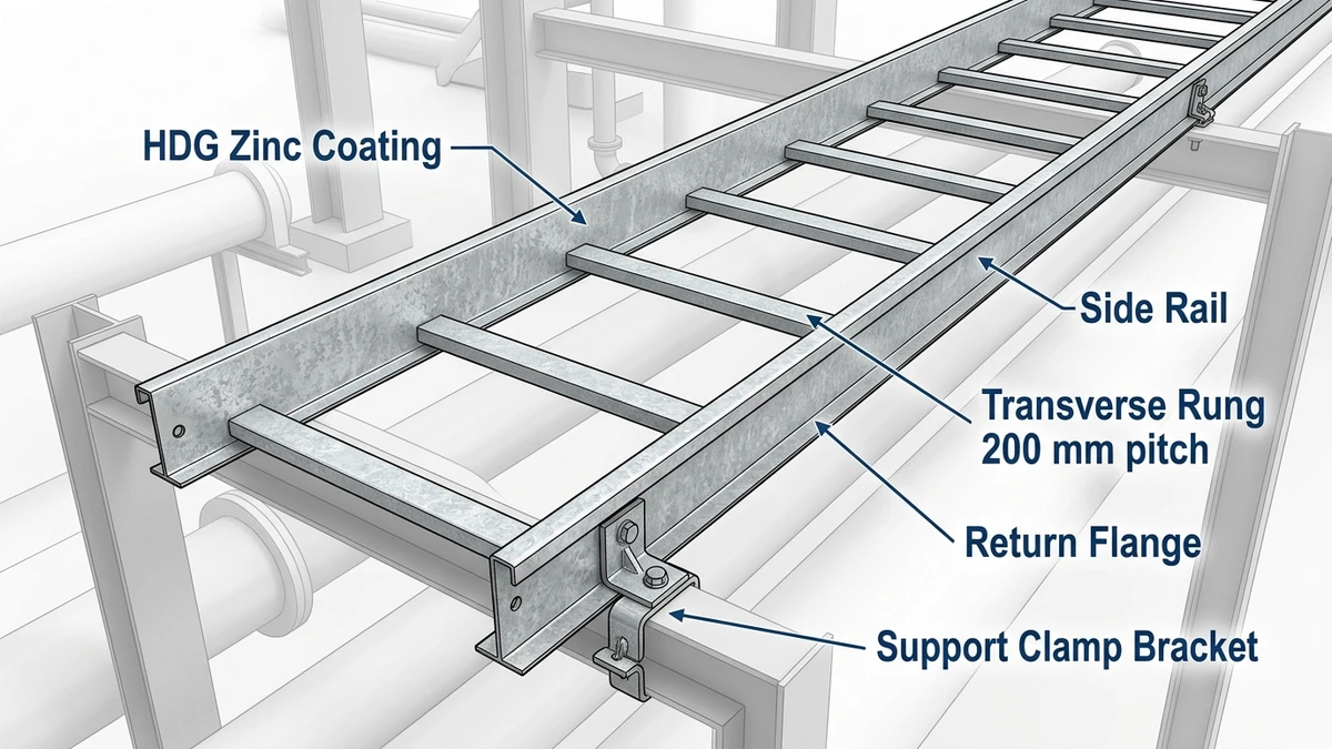
Galvanized steel ladder cable tray is a structural cable management system consisting of two parallel side rails connected by evenly spaced transverse rungs, fabricated from steel and protected by a zinc coating applied through hot-dip or electro-galvanizing processes. It is one of the most widely specified cable routing solutions in industrial, utility, and heavy commercial construction worldwide.
The ladder tray’s open-rung design distinguishes it from solid-bottom or perforated cable tray systems. Side rails typically range from 50 mm to 150 mm in height, with rung spacing of 150 mm to 300 mm depending on the cable diameter being supported — closer spacing at 150 mm is required for cables under 12 mm in diameter to prevent sag between rungs. Standard tray widths run from 150 mm to 900 mm, accommodating everything from small control cable bundles to high-voltage power circuits carrying multiple 240 mm² conductors.
The open architecture serves a dual engineering purpose. It allows natural convective airflow around cables, which reduces thermal derating penalties under IEC 60364-5-52, and it significantly reduces dead weight — a 600 mm wide ladder tray typically weighs 30–50% less per meter than a comparable solid-bottom tray, easing structural support requirements.
Figure 1. Galvanized steel ladder cable tray cross-section showing side rail height (mm), transverse rung pitch (150–300 mm center-to-center), tray width range (100–900 mm), and HDG zinc coating layer depth (45–85 µm) on steel substrate — the four structural parameters that determine load class per IEC 61537.
How Galvanized Steel Ladder Cable Tray Is Manufactured and Coated
Galvanized steel ladder cable tray starts as cold-rolled or hot-rolled steel strip — typically 1.5 mm to 3.0 mm thick — cut and formed into side rails and cross rungs before the galvanizing process bonds a protective zinc layer to every exposed surface.
Steel Forming and Rung Assembly
Side rails are roll-formed or press-braked into a C-channel or Z-profile geometry, giving each rail its bending stiffness. Cross rungs spaced at 150 mm, 200 mm, or 300 mm centers are resistance-welded or mechanically swaged into the rail. Rung spacing directly governs the minimum bending radius cables may rest at; tighter spacing at 150 mm is specified when supporting flexible or small-diameter instrumentation cables that would otherwise sag between supports.
Hot-Dip Galvanizing vs. Pre-Galvanized Coating
After forming and welding, two coating routes are used in commercial production.
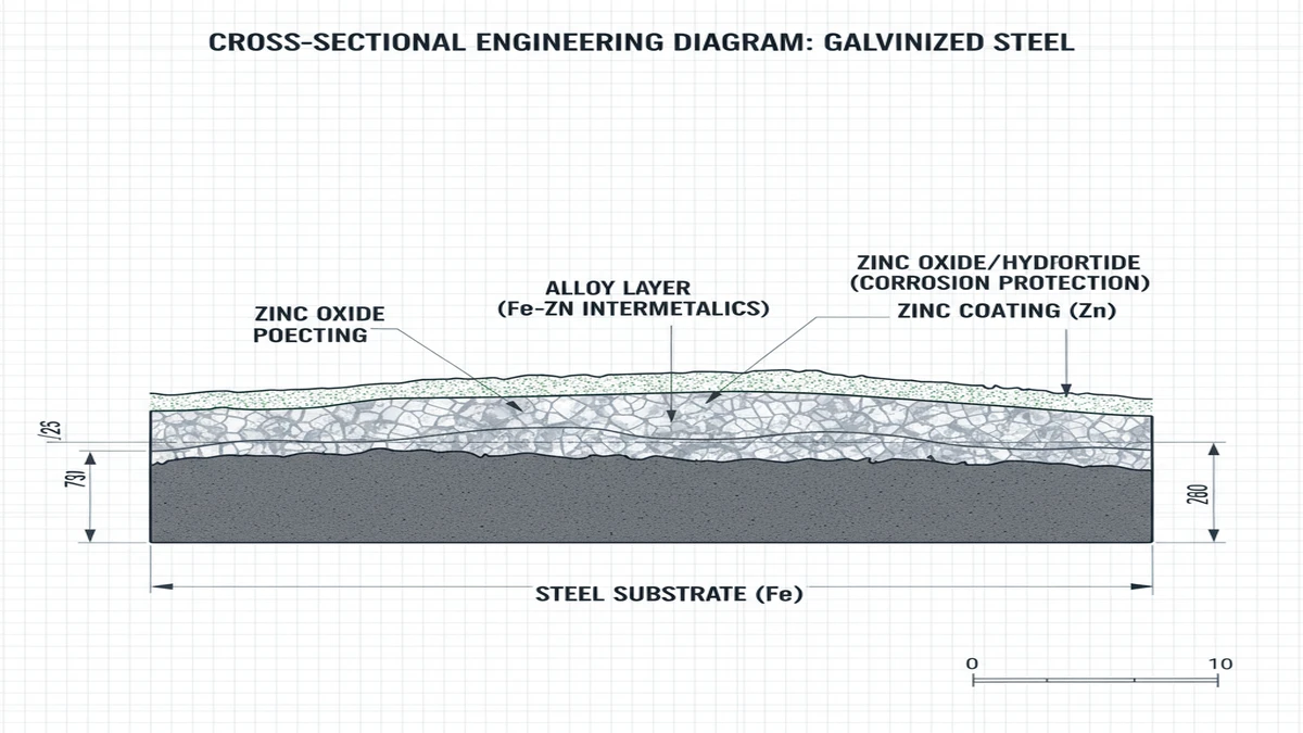
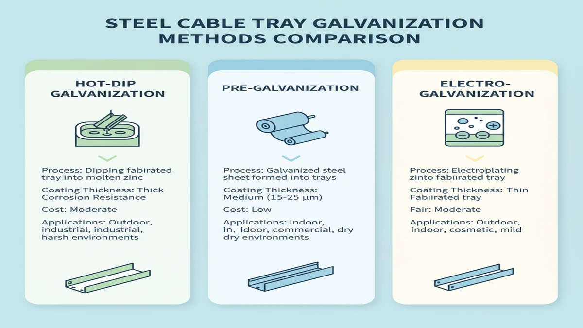
Hot-dip galvanizing (HDG) immerses the finished tray in a molten zinc bath at approximately 450 °C. The zinc metallurgically bonds to the steel, producing a coating thickness of 45–85 µm per ASTM A123 / ISO 1461. This intermetallic layer — iron-zinc alloy sublayers topped by pure zinc — resists mechanical abrasion and sacrificially protects exposed steel at cut edges through cathodic action.
Pre-galvanized (electro-galvanized or continuous-strip galvanized) steel is coated before forming. Coating thickness is typically 7–20 µm, which lowers corrosion resistance but reduces unit cost and maintains tighter dimensional tolerances — an advantage when trays must nest inside narrow cable management channels or when the installation environment is dry and controlled.
Electrogalvanizing applies zinc electrochemically at room temperature, producing a very uniform layer of 5–25 µm. The thin deposit offers limited outdoor service life and is rarely specified for industrial cable routing systems exposed to moisture or chemical atmospheres.
ISO 1461 governs the minimum average coating thickness and adhesion requirements for hot-dip galvanized steel fabrications. ASTM A123 serves the equivalent role for North American specifications. Both standards require the coated article to pass a test for coating uniformity; buyers should request mill certificates confirming compliance before procurement, particularly for outdoor or chemically aggressive cable routing environments.
Figure 2. Zinc coating thickness comparison across three galvanization processes: HDG after fabrication (45–85 µm), pre-galvanized mill coating (10–30 µm), and electro-galvanized (5–15 µm) — with corresponding cut-edge protection status and recommended installation environment for each process type.
[Expert Insight]
– HDG coating thickness is not uniform across all steel thicknesses — sections thinner than 3 mm often achieve only 35–45 µm even under ISO 1461, so always specify the steel gauge alongside the coating class.
– Requesting the mill certificate at procurement, not at delivery, eliminates the risk of discovering non-compliant coating after installation begins.
– Cut edges and drilled holes on HDG trays are protected by cathodic action from the surrounding zinc, but only within approximately 1–2 mm of the breach — larger exposed areas should receive zinc-rich touch-up paint per ASTM A780.
– Pre-galvanized trays can be cost-effective in dry indoor environments, but every field-cut edge is unprotected and should be treated accordingly.
How to Select the Right Galvanized Steel Ladder Cable Tray for Your Application
Selecting the correct galvanized steel ladder cable tray requires matching four interdependent parameters to site conditions: load class, coating grade, rung spacing, and tray width. An undersized tray or mismatched coating creates long-term failure risk that costs far more to remediate than a correctly specified installation from day one.
In a 2023 petrochemical expansion project in Shandong Province (12,000 linear meters of cable routing), specification errors in coating grade forced replacement of approximately 800 m of tray within the first year — adding roughly 15% to the original cable management budget. The selection framework below, structured around IEC 61537, is designed to prevent exactly that outcome.
Step 1 — Determine Your Load Class
Start with the total cable fill weight per linear meter. Sum the mass-per-meter of every cable routed through the tray, add a 20–25% safety margin for future cable additions, and compare against IEC 61537’s four load classes:
Load Class
Rating
Typical Application
Class A
50 kg/m
Light instrumentation runs
Class B
100 kg/m
Standard power and control routing
Class C
150 kg/m
Medium-voltage feeders, dense wiring
Class D
200 kg/m
Heavy power distribution in process plants
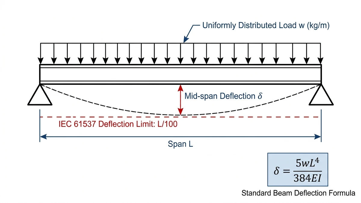
Each class is validated against a proof load of 1.5× the rated uniform distributed load, with maximum allowable midspan deflection set at L/200 under full load. For a 3 m span, that limit is 15 mm.
A 2023 automotive assembly plant expansion in Guangzhou (18,000 m² facility) illustrates the cost of under-specification: the engineering team initially called out Class B trays at 100 kg/m. After the cable schedule was finalized, actual fill reached 138 kg/m. Upgrading to Class C midway through procurement added 11% to material cost and delayed installation by three weeks. A separate project in Ningbo that year got it right from the start — initial calculations showed 87 kg/m across main cable routes, Class B was confirmed adequate, and the project avoided unnecessary overengineering while cutting tray material costs by approximately 22% versus an early Class C draft specification.
Step 2 — Match Coating Grade to Corrosion Zone
Not all galvanized coatings perform equally, and the environment governs which grade is defensible.
Hot-dip galvanizing to ISO 1461 delivers a zinc layer of 45–85 µm on fabricated steel — suitable for outdoor, coastal, and moderately chemically active environments corresponding to ISO 9223 corrosivity categories C3 to C4. For C5 zones (offshore platforms, heavy chloride exposure, acid-mist atmospheres), specify either a heavier hot-dip coat at ≥ 85 µm or evaluate a duplex system combining hot-dip galvanizing with an epoxy powder topcoat, which can extend service life beyond 25 years in aggressive conditions.
Pre-galvanized (mill-galvanized) sheet typically carries only 7–20 µm of zinc and is appropriate exclusively for dry indoor cable routing — C1 to C2 environments under ISO 9223. Electro-galvanized finishes at 5–25 µm suit precision electronics or cleanroom installations where coating uniformity matters more than corrosion margin, but they offer limited service life outdoors.
For buyers: specifying HDG when the installation environment exceeds 60% average relative humidity or involves periodic washdowns is a minimum industry practice, not an overreach.
Step 3 — Select Rung Spacing for Cable Diameter
Rung spacing controls sag between support points for individual cables. As a practical rule, rung pitch should not exceed 6× the outer diameter of the largest unsupported cable. Standard spacings are 150 mm, 200 mm, and 300 mm.
For cables with an outer diameter below 25 mm, 300 mm pitch is generally acceptable. For larger-diameter cables or bundles exceeding 50 mm overall diameter, 150 mm pitch prevents excessive sag and reduces mechanical stress on cable sheaths. For cables above 75 mm OD — such as 11 kV medium-voltage feeders — the 150 mm spacing also maintains fire performance ratings by preventing contact bunching.
Step 4 — Size Tray Width Using Fill Ratio
A fill ratio of 40–50% of usable tray cross-section is the accepted design ceiling, preserving thermal dissipation space and room for future cable additions. Standard widths are 150 mm, 300 mm, 450 mm, 600 mm, and 900 mm. A 600 mm wide tray with 100 mm side rails offers approximately 60,000 mm² of usable cross-section; plan cable bundles to occupy no more than 30,000 mm² to stay within thermal derating limits.
For span configuration: support spacing of 1.5 m to 3 m is standard for most industrial installations. Reducing the support interval from 3 m to 2.4 m for a Class C, 600 mm wide tray brings midspan deflection from approximately 15 mm to below 10 mm — a useful reserve for future cable additions without re-engineering the support structure.
Selection Checklist
Parameter
Key Decision Point
Typical Range
Load class
Calculated fill + 20–25% margin
50–200 kg/m
Zinc coating thickness
Environment severity (ISO 9223 category)
45–85 µm (HDG)
Tray width
Fill ratio ≤ 40–50% of cross-section
150–900 mm
Rung spacing
Max 6× largest cable OD
150–300 mm
Figure 3. Simply supported ladder cable tray under uniformly distributed load (UDL) showing mid-span deflection δ and the IEC 61537 deflection limit of L/100, where L is the span between supports — the basis for load class assignment in IEC 61537 test methodology.
[Expert Insight]
– Always confirm midspan deflection against L/200 before accepting a lighter load class — the math takes minutes and avoids costly mid-project upgrades.
– ISO 9223 corrosivity categories are the most reliable framework for matching zinc coating thickness to environment; request a site corrosivity assessment if the project is near the coast or within a chemical process zone.
– A duplex system (HDG + epoxy topcoat) at C4–C5 sites typically costs 15–20% more upfront but can double effective service life, making it the lower lifecycle-cost option on projects with 25-year maintenance targets.
– For control cable routing alongside power circuits, verify that rung spacing also satisfies the cable manufacturer’s minimum support interval — this is occasionally tighter than the IEC 61537 default.
Key Performance Characteristics and Field Observations
Understanding how galvanized ladder cable tray performs across its service life — not just at commissioning — is what separates a well-specified system from one that generates maintenance calls in year three.
Corrosion Resistance in Service
Zinc coating applied through hot-dip galvanizing produces a metallurgically bonded layer of 45–85 µm per ASTM A123/A123M and ISO 1461. In moderately corrosive industrial environments, HDG ladder trays typically achieve 20–30 years of service before requiring inspection or replacement. Electroplated trays in the same conditions may show red rust within 5–8 years — a meaningful lifecycle cost difference when cable tray represents a significant share of a facility’s cable management infrastructure.
In a petrochemical plant expansion in Shandong Province covering approximately 18,000 m² of process areas, the specification team selected hot-dip galvanized ladder cable tray for all outdoor and semi-enclosed cable routing zones. The decision was driven by a corrosion risk assessment showing ambient chloride levels above 0.3 mg/m²·day — a threshold at which zinc coatings below 45 µm would not meet the project’s 25-year maintenance-free target. Post-installation inspection at 18 months showed zero measurable red rust at cut edges or drilled holes, attributed to the cathodic protection margin of the 72 µm average zinc layer achieved.
Structural Performance Under Load
The ladder configuration’s open-rung geometry concentrates bending stress in the side rails, which is why rail height is the primary variable governing load class. Increasing side rail depth from 75 mm to 150 mm on a Class B tray typically shifts it into Class C capability at equivalent span lengths — a detail worth discussing with the manufacturer’s engineering team during specification, since it can avoid the cost of moving to a heavier product series entirely.
Support interval is equally critical. For a 600 mm wide, Class C ladder tray spanning 3 m, deflection under proof load typically reaches 12–15 mm. IEC 61537 limits deflection to L/200, which for a 3 m span equals 15 mm maximum. Adding a mid-span support bracket effectively halves the span and can allow the next lower load class, reducing material cost on long cable routing runs.
Thermal Management Advantage
The open-rung design’s ventilation benefit is measurable. Under IEC 60364-5-52 ampacity derating tables, cables installed in open cable tray typically require less derating than cables in enclosed conduit or solid-bottom trays — a direct operating cost benefit on large conductor sizes where the difference between 240 mm² and 300 mm² conductors represents significant copper cost. For the complete range of structural and load specifications, the ladder cable tray product series covers standard and heavy-duty load classes. The load class testing methodology is governed by IEC 61537, the international standard covering cable tray and cable ladder systems.
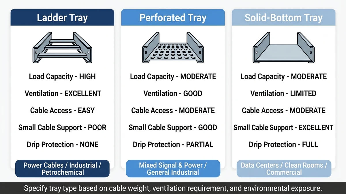
Figure 4. Cross-section comparison of ladder, perforated, and solid-bottom cable tray types across five selection criteria — load capacity, ventilation, cable access, small cable support, and drip protection — for industrial, mixed-signal, and data center applications respectively.
How do I calculate the correct load class for a galvanized steel ladder cable tray installation?
Sum the mass-per-meter rating of every cable to be routed through the tray, then apply a 20–25% margin for future cable additions before comparing against IEC 61537’s four load classes — Class A at 50 kg/m through Class D at 200 kg/m. Running the calculation at the cable schedule stage, rather than after procurement, avoids the mid-project upgrades that added 11% to material cost in at least one documented 2023 installation.
What is the practical difference between hot-dip galvanized and electro-galvanized ladder cable tray in outdoor environments?
Hot-dip galvanized tray carries a zinc layer of 45–85 µm that is metallurgically bonded to the steel and provides cathodic protection at cut edges; electro-galvanized tray typically has 5–25 µm that offers limited protection once the steel is exposed. In outdoor or high-humidity environments, the service life difference between the two methods can span 15–25 years, making HDG the more defensible choice despite higher upfront cost.
Which rung spacing should I specify for medium-voltage power cables?
For cables above 50 mm outer diameter — including 11 kV medium-voltage feeders — a 150 mm rung pitch is generally recommended to prevent excessive sag between supports and reduce mechanical stress on cable insulation. The practical guideline is that rung pitch should not exceed six times the outer diameter of the largest unsupported cable in the run.
How does tray fill ratio affect cable ampacity?
Packing cables too densely reduces airflow around conductors, increasing operating temperature and requiring ampacity derating under IEC 60364-5-52. Keeping the cable fill ratio at or below 40–50% of the tray’s usable cross-sectional area preserves natural convection, maintains rated ampacity for the installed conductors, and leaves space for future circuit additions without requiring a wider tray.
Can galvanized steel ladder cable tray serve as a protective earthing conductor?
Under IEC 61537 and many national electrical codes, a continuously bonded galvanized steel cable tray may qualify as a protective earthing conductor, provided all splice joints are bonded with listed hardware and measured continuity resistance stays below 0.1 Ω across each joint. Site-specific electrical codes and the project’s earthing philosophy should be reviewed before relying solely on tray continuity.
When should I consider a duplex coating system instead of standard hot-dip galvanizing?
A duplex system — hot-dip galvanizing combined with an epoxy or polyester powder topcoat — is worth evaluating for installations in ISO 9223 C4 to C5 corrosivity zones, such as offshore platforms, coastal chemical plants, or environments with regular acid-mist exposure. The combination typically adds 15–20% to coating cost but can more than double effective service life compared to HDG alone, making it the lower lifecycle-cost option on projects with 25-year or longer maintenance-free targets.
What span length requires an intermediate support bracket on standard ladder cable tray?
Most standard industrial ladder cable tray installations use support intervals of 1.5 m to 3 m. When the required span exceeds 3 m, or when midspan deflection under full load approaches the IEC 61537 limit of L/200, adding an intermediate bracket at the midpoint effectively halves the deflection and can allow the next lower load class — reducing material cost on long cable routing runs without compromising structural compliance.
Kevin Zheng
Kevin Zheng is a manager linked to Shanghai Xinma Busway & Cable Tray Co., Ltd. He writes technical content on cable tray systems, installation practice, sizing logic, load classes, and related standards for industrial and infrastructure applications.