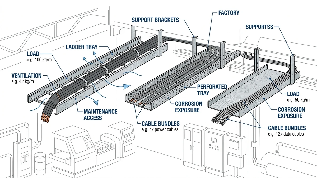
Galvanized steel cable tray for general industrial use is a zinc-coated steel support system for routing power, control, and instrumentation cables in open runs. It is commonly used where engineers need moderate corrosion resistance, predictable structural capacity, and easier inspection than conduit, typically across 1.5-3.0 m spans and 100-600 mm tray widths.
In practice, steel provides stiffness and impact resistance, while zinc delays corrosion through sacrificial protection. Selection usually depends on corrosion exposure, tested load class, and support span rather than finish name alone. Under IEC 61537, tray systems are evaluated by tested load and deflection performance, so verified load class matters more than sheet thickness by itself.
A tray suitable for 40-80 kg/m in a dry utility building may be a poor choice in washdown zones or areas with persistent vapor or wet deposits. In those cases, finish type, splice details, or even the base material may need to change.
Why Galvanized Steel Cable Tray Is Common in Factories and Utility Buildings
Galvanized steel cable tray is widely used because it balances structural strength, cost, and maintainability. It is generally stiffer than many lightweight alternatives, less expensive than stainless steel in ordinary indoor service, and easier to inspect or modify than closed raceway.
In controlled indoor areas, it usually performs well where humidity is moderate and chemical exposure is limited. Hot-dip galvanized coatings are typically thicker than pre-galvanized finishes, often about 45-85 μm, so they usually resist edge damage, scratches, and contamination better in harsher service.
Engineering trade-offs that actually drive selection
Parameter
Design advantage
Constraint to check
Structural capacity
Steel side rails support heavier cable loads and wider trays, commonly 300-900 mm wide over 1.5-3.0 m spans
Higher self-weight increases hanger loads, support steel, and seismic restraint demand
Corrosion resistance
Zinc coating slows corrosion in normal industrial atmospheres
Chlorides, strong alkalis, or persistent wet service can shorten life quickly
Cost position
Usually lower first cost than stainless steel at the same load class
Lifecycle cost can rise if recoating, early replacement, or frequent maintenance is needed
Electrical continuity
Metal tray may serve as part of the equipment bonding path where permitted and properly installed
Joint resistance can rise at painted interfaces, corroded splices, or poorly torqued hardware
Inspection and retrofit
Open tray simplifies cable adds, fill checks, and fault tracing
Dust accumulation and exposed routing may increase cleaning needs
Thermal behavior
Open metal tray handles higher ambient heat better than many non-metallic systems; 40-50 °C service areas are common
Cable ampacity is still governed by grouping, fill, and ambient temperature
In boiler houses, indoor substations, and utility zones, the main benefit is often structural margin rather than premium corrosion resistance. The main risk is environmental misclassification: an “indoor” route can behave like a semi-corrosive area once condensate, washdown water, or residue is present.
[Expert Insight]
If the route is above process equipment, inspect the underside exposure, not just the room classification. Rising vapor and warm condensate often attack fittings first.
For ordinary factory utility runs, a heavier zinc coating often adds more practical service life than increasing tray thickness alone.
If future cable additions are likely, reserve load margin at the initial support spacing; retrofitting extra hangers later is usually more disruptive than specifying them early.
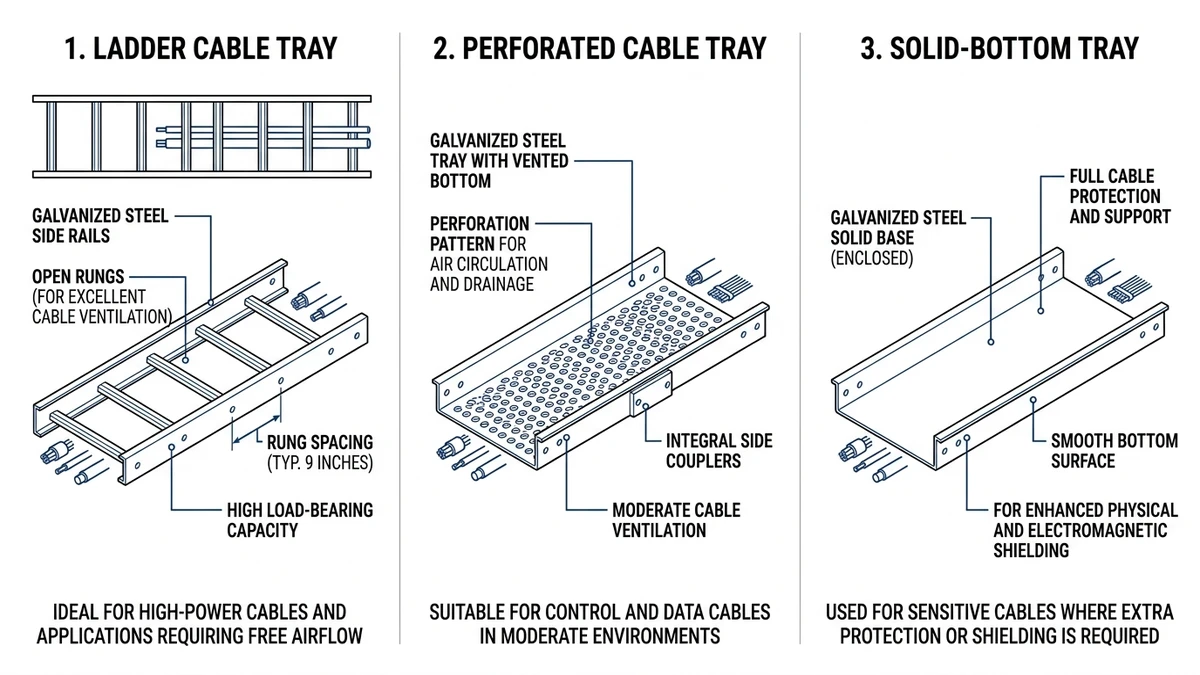
How Tray Type Affects Performance: Ladder, Perforated, and Solid-Bottom Options
Tray type affects cooling, cable support, dust retention, self-weight, and maintenance access. The choice should be based on the dominant need: heat dissipation, contamination control, or support for mixed cable sizes.
Engineering comparison of common tray forms
Tray type
Mechanism
Typical cue
Best use case
Main penalty
Ladder tray
Open rungs promote airflow and reduce self-weight
Rung spacing typically 200-300 mm
Heavier power cables, longer pulls, better heat dissipation
Limited support for small cables unless retainers or accessories are added
Perforated tray
Ventilated bottom provides continuous support with partial airflow
Sidewall typically 50-150 mm
Mixed power, control, and instrumentation runs
Lower thermal performance than ladder tray
Solid-bottom tray
Continuous pan blocks falling debris and overhead drips
Bottom sheet commonly 1.0-2.0 mm thick
Sensitive control cables or dirty overhead areas
Higher heat retention, more self-weight, slower inspection
What changes in real design work
The main trade-off is thermal margin versus protection. Ladder tray usually offers the best natural convection and is often preferred for higher-load power circuits, while solid-bottom tray protects better from falling dust or drips but can require more ampacity review because heat dissipation is poorer.
Self-weight also changes with tray form. On the same width and span, a solid-bottom tray typically adds more steel mass than a ladder tray, increasing hanger load and support demands.
There are installation effects as well. Ladder tray eases cable pulling and tie-down access, while perforated tray better supports small control and instrumentation cables that might sag between rungs.
A practical example is VFD output cables in a 40 °C indoor plant area: ladder tray is usually easier to justify because thermal margin matters more than debris shielding.
Use when / avoid when / check before specifying
Use when
Use ladder tray when power cable heat, pulling access, or lower self-weight drives the design. Use perforated tray when cable sizes are mixed and bottom support matters. Use solid-bottom tray when overhead contamination is the main problem.
Avoid when
Avoid ladder tray where small control wiring lacks support or falling debris is likely. Avoid solid-bottom tray where ambient temperature is already high and cable grouping is dense. Avoid perforated tray as a default if thermal or contamination demands clearly favor another form.
Check before specifying
Check cable size mix, expected fill, ambient temperature, cleaning method, and future cable additions. Also verify that the selected tray type still meets the required load class at the intended support spacing.
Figure 1. Galvanized steel cable tray configurations compared by ventilation, cable support continuity, and contamination resistance for industrial routing.
[Expert Insight]
Testing and field adjustments often show that tray type errors reveal themselves first during cable pulling, not after energization; unsupported small cables or congested bends are common early warnings.
If a route carries both large power cables and fragile instrumentation, splitting the run into two tray types can be cleaner than forcing one compromise tray across the entire route.
Covers solve contamination problems only partly; they also change heat dissipation and maintenance access, so treat them as a system decision, not an accessory decision.
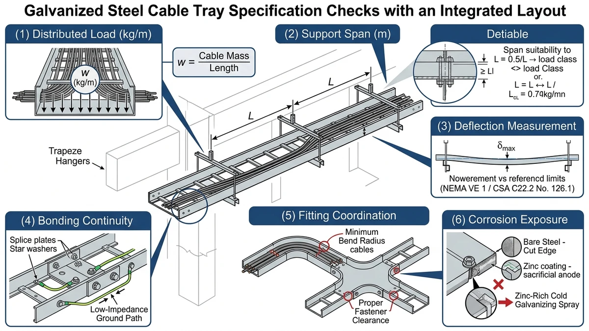
What Engineers Check Before Specifying Galvanized Steel Cable Tray
Before specifying galvanized steel cable tray, engineers usually check corrosion environment, mechanical loading, electrical continuity, thermal behavior, and installation geometry. The tray must be selected as a system, not as a standalone metal channel.
Corrosion environment and coating thickness
The first check is whether the galvanizing method matches the atmosphere. Pre-galvanized sheet is often suitable for dry indoor service, while hot-dip galvanized after fabrication is usually preferred where washdown, outdoor exposure, or mild chemical contact is expected because welds, cut edges, and fittings receive more complete coverage.
This matters because corrosion usually appears first at cut edges, bolted joints, and supports. A 55-85 μm hot-dip coating will generally last longer in exposed service than lighter indoor coatings.
Load, span, and deflection
The next check is structural performance. A 300 mm tray carrying 25 kg/m of control cable is a very different case from a 600 mm tray carrying 75 kg/m of power cable over a 3.0 m span, so engineers should use tested load tables and confirm allowable deflection, often around span/200 unless the project requires less.
If support spacing exceeds the design assumption, the result is not just visible sag. Excess deflection can overload splice plates, distort covers, and reduce confidence in future cable additions.
Electrical bonding and fault path integrity
Galvanized steel cable tray may form part of the equipment bonding path where code and project practice allow it. If so, splice resistance, bonding jumpers, hardware finish, and clean contact surfaces need to be controlled because paint, corrosion products, or vibration-isolated supports can raise joint impedance.
The main engineering point is fault performance. A discontinuous or high-resistance path can affect fault current return and protection coordination.
Cable fill, heat, and access
Cable fill affects heat rejection, pulling difficulty, and future maintenance. Dense multicore power cables at 40-50% fill may need ampacity review, especially in covered or solid-bottom tray, while control cable bundles that physically fit may still be difficult to trace or separate later.
Figure 2. Engineering review points for galvanized steel cable tray selection, including load, support span, bonding continuity, fittings, and corrosion exposure.
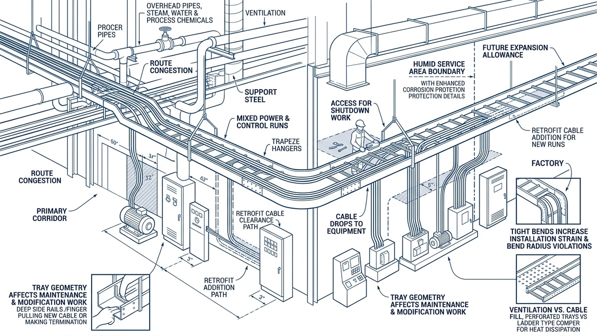
How Galvanized Steel Cable Tray Behaves in Real Industrial Conditions
Galvanized steel cable tray performs well when exposure stays within its limits: moderate humidity, ordinary indoor dust, occasional washdown, and normal mechanical abuse. It becomes a shorter-life option where standing water, chlorides, or aggressive cleaning chemicals are routine.
Dry indoor process and utility areas
In motor control rooms, service corridors, and utility spaces, mechanical load often governs more than corrosion rate. With spans of 1.5-3.0 m and cable loads of 40-100 kg/m, galvanized steel tray is often a practical choice if water does not collect and field-cut surfaces are controlled.
Ladder tray is usually preferred for heavier power circuits because it dissipates heat and simplifies clamping, while perforated tray often suits mixed control wiring that needs continuous bottom support.
Humid or washdown-prone indoor zones
Pump rooms, food-adjacent utility spaces, and enclosed process bays often become more corrosive than drawings suggest once condensation and cleaning cycles begin. Repeated wetting keeps zinc surfaces active longer, especially at low points, splice plates, and under bundled cables.
In these zones, the finish often shifts from pre-galvanized to hot-dip galvanized, and drainage and support detailing become more important. The first warning is often red rust around hardware and fittings rather than rail failure.
Outdoor and contaminated routes
Outdoor cable management adds rain, deposits, and thermal cycling. Zinc can perform adequately in many sheltered outdoor settings, but airborne chlorides, sulfur compounds, and process dust can sharply increase corrosion rates, especially at bolted joints and horizontal surfaces where deposits stay wet.
The key decision is to review material, fitting finish, drainage, covers, support details, and inspection interval together. If contamination is regular and difficult to remove, a different material system may be more appropriate than simply specifying more zinc.
For support planning on long industrial routes, especially where vertical offsets and field adjustments are likely, this reference on support spacing and hanger strategy is useful when checking whether the intended span still matches the installed load condition.
Figure 3. Typical industrial field conditions affecting galvanized steel cable tray choice, including overhead congestion, maintenance access, and future cable additions.
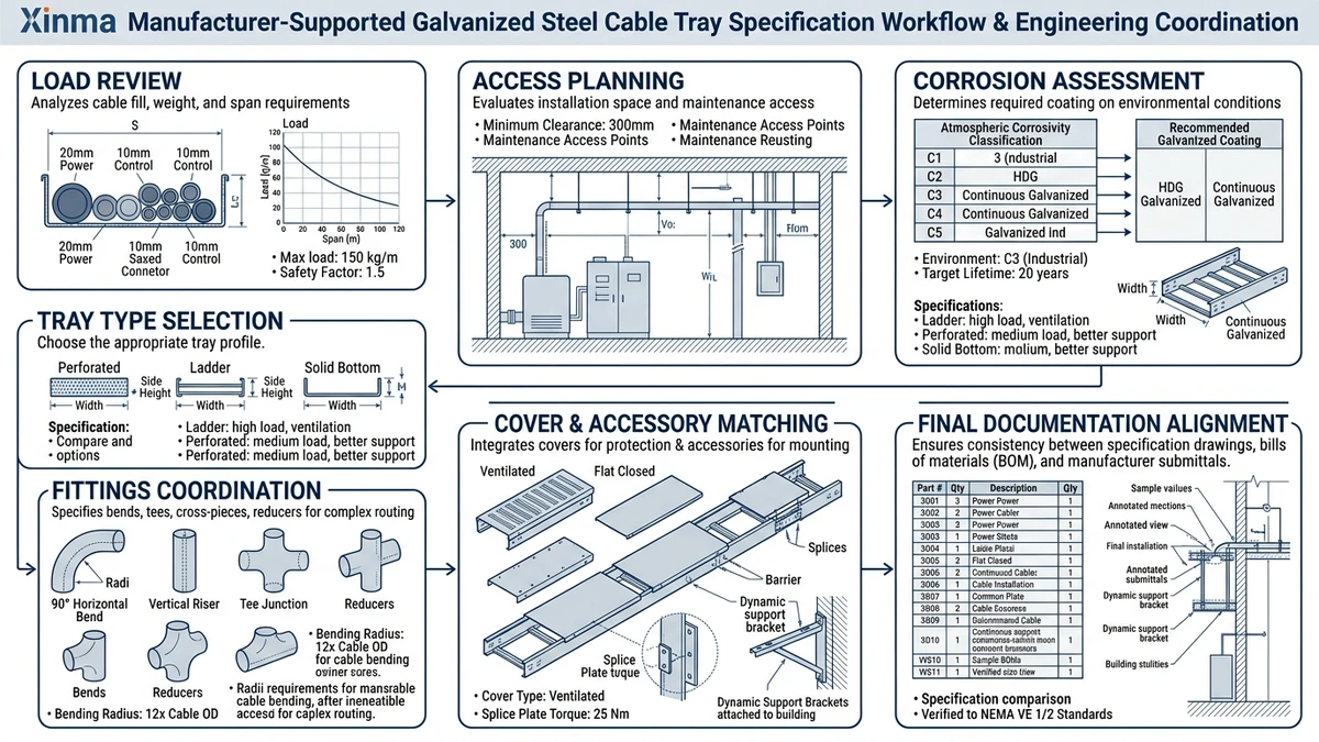
How Xinma Helps Coordinate Loading, Access, Corrosion, and Fittings Decisions
By procurement stage, most costly tray mistakes come from earlier assumptions such as incorrect support span, unsuitable finish, or fittings that do not preserve continuity across the run. Manufacturer coordination is useful mainly because it helps catch those mismatches before installation.
Xinma typically reviews tray type, width, side rail depth, zinc protection, fittings compatibility, and cover strategy against actual support spacing and cable load. A tray rated at 75 kg/m or 100 kg/m can still become inadequate if tees, reducers, covers, future growth, or localized point loading are added later.
Where coordinated review changes the outcome
A technically useful review usually covers:
whether tray width and side rail depth still match cable fill and future reserve
whether 2.0 m, 2.5 m, or 3.0 m support spacing still satisfies the intended load class and deflection target
whether bends, tees, reducers, couplers, and splice plates remain mechanically compatible through the whole run
whether the corrosion environment calls for pre-galvanized steel, hot-dip galvanized steel, or another material approach
whether accessories and restraint details are consistent with the support concept
This is also where accessory selection matters. Mixed fitting geometry, overstressed spans near vertical drops, and finish mismatches between straight lengths and hardware are common late-stage issues. Where seismic demand or high support reaction is relevant, coordination with restraint and bracing details should happen before the tray schedule is finalized. On projects comparing busway with tray-fed distribution corridors, this overview of busway applications and distribution architecture can help frame the system choice.
If your project needs galvanized steel cable tray selected around real loading, corrosion exposure, fitting continuity, and maintenance access—not just tray width on a bill of materials—Xinma can help review the route before release.
How do I choose between pre-galvanized and hot-dip galvanized cable tray?
Pre-galvanized tray is often suitable for dry indoor areas with limited corrosion risk, while hot-dip galvanized tray is usually the better choice where cut edges, outdoor exposure, washdown, or persistent moisture are expected.
What support spacing is typical for galvanized steel cable tray?
Many industrial layouts use support spans in the 1.5-3.0 m range, but the correct spacing depends on tray width, cable load in kg/m, fitting locations, and the tested load-deflection performance of the selected system.
Is ladder tray better than perforated tray for power cables?
Ladder tray is often preferred for heavier power circuits because airflow is better and cable pulling is easier, but perforated tray may be the better fit when smaller cables need continuous bottom support.
When should galvanized steel cable tray be avoided?
It is generally a weaker choice where chlorides, aggressive cleaning chemicals, or long-term wet deposits are part of normal operation, since those conditions can shorten coating life and increase maintenance demand.
How much spare capacity should I leave in a cable tray?
Many engineers keep reserve space for future cable additions and maintenance access rather than filling the tray close to its geometric maximum, because thermal behavior, segregation, and pulling difficulty usually worsen as fill increases.
Can cable tray be used instead of conduit in industrial buildings?
It can be a practical alternative for many open industrial runs where inspection access, cable changes, and grouped routing are important, but the decision still depends on environment, mechanical protection needs, and project code requirements.
Kevin Zheng
Kevin Zheng is a manager linked to Shanghai Xinma Busway & Cable Tray Co., Ltd. He writes technical content on cable tray systems, installation practice, sizing logic, load classes, and related standards for industrial and infrastructure applications.