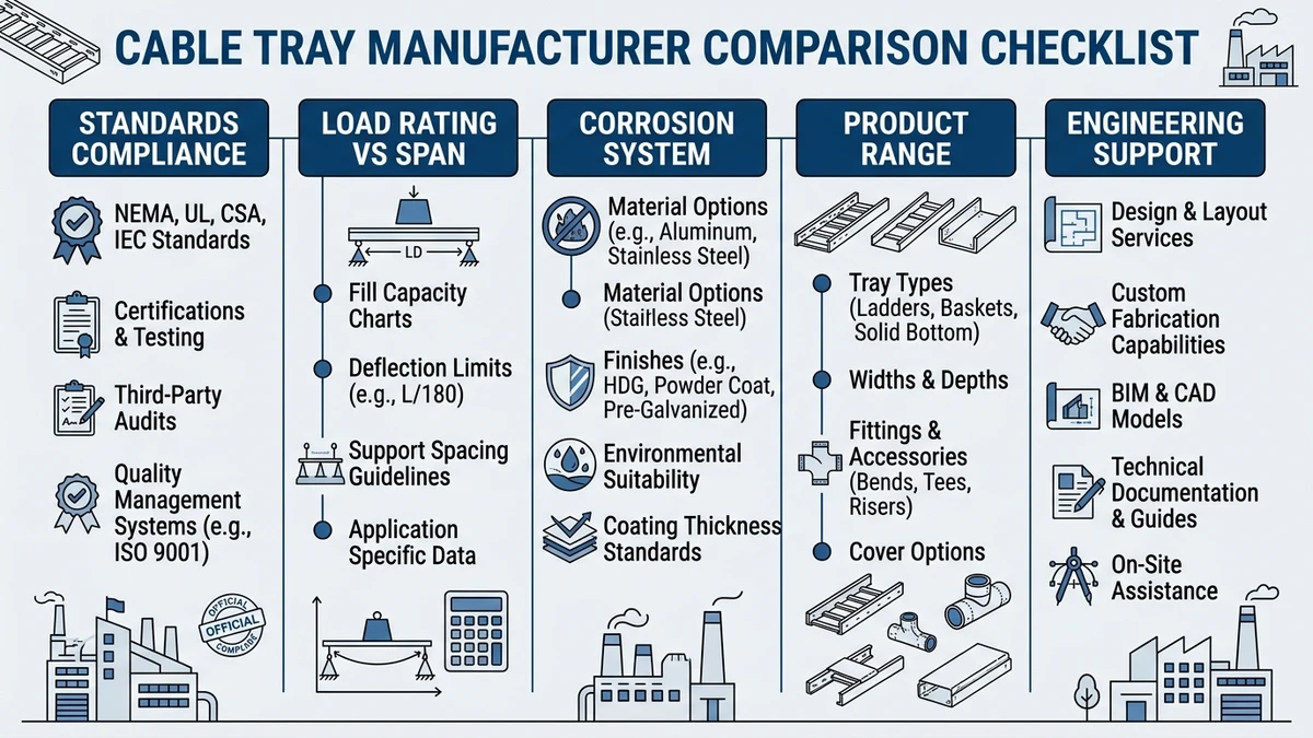
2026 Checklist Snapshot: How to Compare Cable Tray Manufacturers
To compare cable tray manufacturers in 2026, evaluate each as a system supplier, not just a hardware source. Verify compliance with IEC 61537 or NEMA VE 1 load classes, test data, corrosion protection options, and consistent quality across widths from 100–900 mm. Then compare them on load/span performance, system completeness, and how well they support your installation sequence and lifecycle.
Core Technical Criteria: Standards, Loads, and Corrosion Systems
When you compare cable tray manufacturers in 2026, the first filter should be objective technical criteria: which standards they certify to, what loads their systems carry at a given span, and how their corrosion systems match your environment and lifecycle.
Standards and Test Regimes
Ask which core standard governs their cable management system (IEC 61537, NEMA VE 1, or relevant BS/GB equivalents) and request test reports, not just catalog claims. Confirm load test span, deflection limit (L/200 vs L/300), safety factor, and corrosion tests (salt spray hours, adhesion, cyclic tests). Because different standards and test setups are not directly comparable, normalize ratings to a common span and deflection limit (for example, 3.0 m, L/200; IEC 61537 Annex E load classes are a useful reference).
Loads, Span, and Stiffness
For ladder, perforated, wire mesh, and solid tray, compare rated UDL (kg/m) at defined span, maximum support spacing, and midspan deflection and ratio (L/δ). These values determine hanger spacing, seismic bracing, and how much spare capacity you retain for future cables. On a 60 m corridor run, a system rated 200 kg/m at 2.5 m vs 150 kg/m at 3.0 m changes hanger count from 24 to 20, affecting both cost and coordination with other trades.
Corrosion Protection Systems
Corrosion protection drives service life and maintenance, so compare base material (pre‑galv, HDG, aluminum, stainless), coating type/thickness, and environment class (indoor, outdoor inland, coastal, chemical). A 70 μm zinc layer might last 20+ years in mild indoor C2 conditions but only about 8–12 years in coastal C4, while aluminum reduces weight but can pit in chloride/alkaline environments, and stainless 316 offers high chloride resistance at higher cost. In practice, use HDG ≥70 μm or aluminum outdoors and in parking structures, and reserve stainless (304/316) for harsh chemical areas or locations where access for replacement is very limited.
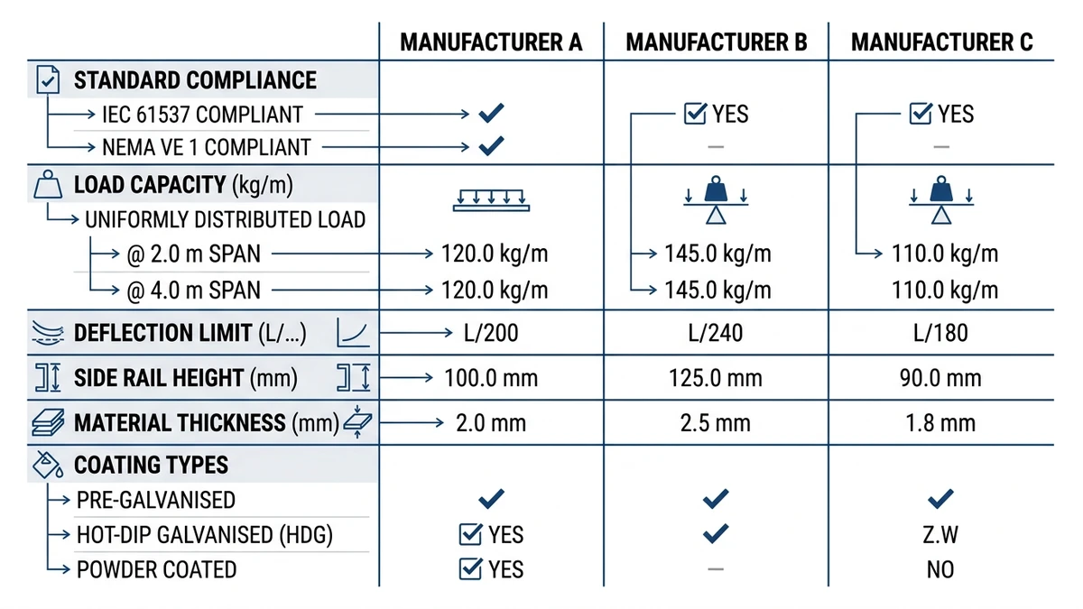
Parameter-Based Comparison Table
Comparison Parameter
Manufacturer A Example
Manufacturer B Example
Design Consequence
Primary standard
IEC 61537
NEMA VE 1
Different load classes, test spans, and terminology
Rated load (300 mm ladder tray)
150 kg/m @ 3.0 m span
200 kg/m @ 2.5 m span
A needs fewer supports; B carries more load per span
Deflection limit
L/200
L/300
B gives stiffer tray and better cable support
Safety factor on working load
1.5×
2.0×
B has more margin for future cable additions
Coating system
Pre‑galv (20 μm)
HDG after fabrication (80 μm)
B better for outdoor/industrial exposure
Suggested environment
Indoor, low humidity
Outdoor, coastal, light chemical
Mismatch here leads to premature corrosion or overspec
Use a parameter‑by‑parameter matrix with your project loads, spans, and environments so manufacturer comparisons are technically clear and repeatable.
[Expert Insight]
– In load tests at 3.0 m spans, the largest differences were often deflection, not ultimate strength; trays with similar “kg/m” ratings behaved very differently at L/200 vs L/300.
– Fixing both span and deflection criteria early makes it easier to reject catalogs that rely on short‑span ratings to appear stronger.
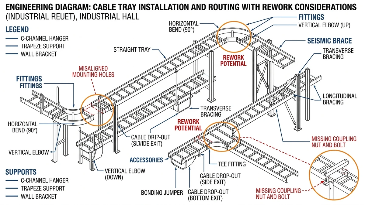
System Completeness and Real-World Installability
“System completeness” often determines whether a tray layout installs quickly or becomes a source of field rework. You are buying a full cable management system that must align with your building, sequence, and crew capabilities.
Check the Fittings Library, Not Just Straight Sections
Confirm that standard widths and depths have matching bends, tees, crosses, reducers, risers, and adjustable couplers, and ask for a layout‑specific BOM to see what share can be supplied from catalog parts. If more than about 10% of direction changes require field‑fabricated fittings, expect longer installation times, inconsistent dimensions, and variable bonding performance.
Supports, Hangers, and Seismic Components as a Package
Check whether the manufacturer supplies compatible supports—cantilevers, trapeze hangers, floor stands—and seismic bracing kits with certified load and acceleration data. Mixing tray from one brand with supports from another can force conservative derating of spans and raise hanger counts, while matched tray/support packages preserve tested combinations and simplify coordination with structure and other services.
Grounding, Bonding, and Accessories
A complete system includes tested bonding jumpers and splice plates, matching drop‑outs, barriers, splice covers, expansion joints, and corrosion‑compatible fasteners. Verify that there are standard details for expansion joints at long runs and building movement joints, and that accessories exist for cable exits, power/data segregation, and firestopping, as these elements strongly affect inspection outcomes and final approvals.
Installation Documentation and Field Flexibility
Review support spacing tables, torque values, bonding instructions, and rules for field modification such as cutting rungs or drilling side rails. As a practical threshold, installers should be able to build roughly 90% of what is shown on the drawings using standard tray, fittings, and supports from the catalog; otherwise, site productivity and consistency will suffer.
[Expert Insight]
– Long industrial pipe racks designed with a single manufacturer’s fittings typically need 10–15% fewer site adjustments than mixed‑brand systems due to consistent hole patterns and tolerances.
– Where more than one in 10 direction changes required custom fabrication, recorded labour hours per meter of tray often doubled, especially on elevated or congested racks.
Commercial and Operational Filters: Lead Time, Scalability, and Total Cost
Commercial performance—lead time, scalability, and lifecycle predictability—often differentiates vendors more than headline load class.
Lead Time and Delivery Risk
Request standard and worst‑case lead times separately for straight tray, non‑standard widths, special finishes, fittings, and covers, and pay attention to variability rather than averages alone. Even if a vendor ships straight sections in 10–14 days, fittings at 25–30 days can become the bottleneck and delay cable pulling; prefer suppliers who can ship tray, fittings, and covers on a synchronized schedule aligned with your installation sequence.
Scalability and Flex Capacity
Scalability is the ability to absorb design growth and late changes without disrupting the schedule, so ask about short‑notice output increases (for example, ≥30% for limited periods), buffer stock for common widths, and their ability to match geometry and finish for expansions 12–24 months later. On multi‑phase campuses or data centers, mismatched tray generations complicate splicing and supports and can weaken cable segregation and labeling consistency over time.
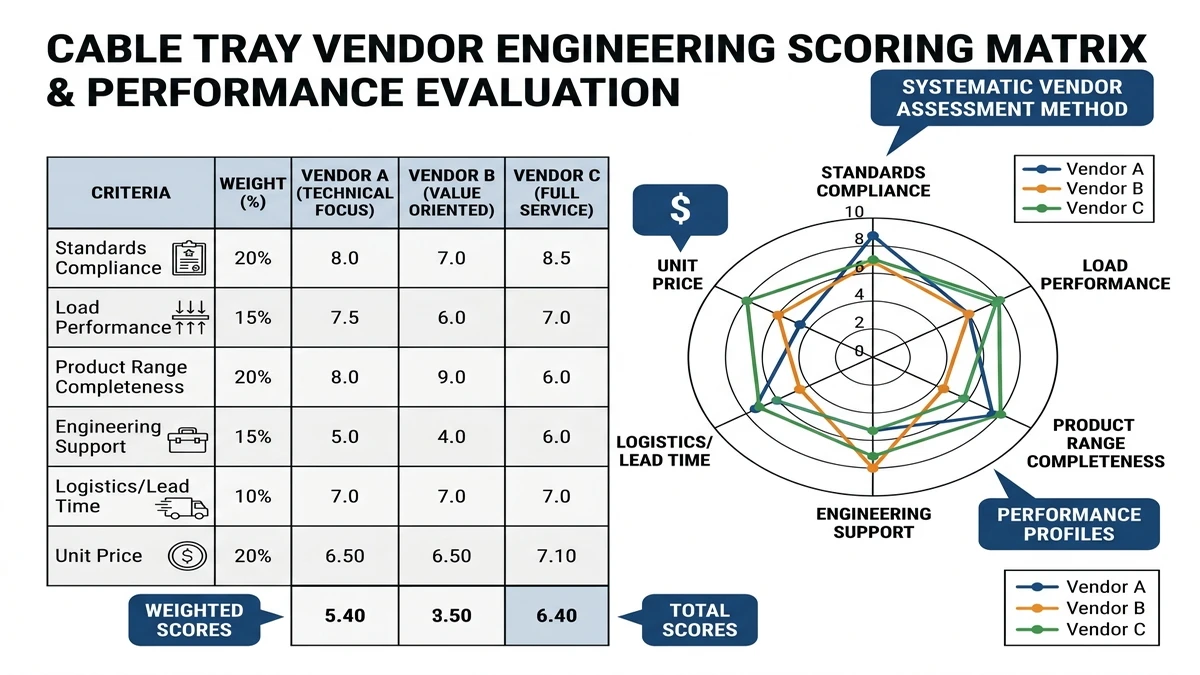
Total Cost: Beyond the Tray Unit Price
Use a weighted scoring matrix that includes unit price, lead‑time reliability, change‑order responsiveness, technical support, logistics quality, installed productivity, and after‑sales service, then compute each vendor’s total score as Σ(weight × score)/100.
Criterion
Weight (%)
Vendor A Score (1–5)
Vendor B Score (1–5)
Unit price (material only)
25
Lead time reliability
20
Change-order responsiveness
15
Engineering/technical support
10
Logistics & packaging quality
10
Installed productivity (field)
10
Warranty & after-sales service
10
Explicitly consider “installed productivity”: systems with simple, symmetric splices and consistent hole patterns often support ≥30 m of tray per 2‑person shift, while designs with many loose parts or asymmetric fittings can cut productivity roughly in half. When these labour and delay impacts are accounted for, the lowest material price is often not the lowest total cost.
Applying the Checklist with Xinma: Coordinating Load, Corrosion, and Support Details
Across real projects, most cable tray rework stems from misjudged load class, under‑specified corrosion protection, and poorly coordinated support spans. With Xinma involved early as a system supplier, these can be addressed together instead of as separate line items.
Load Class vs. Actual Cable and Covers
Begin with actual cable data and support spacing so that tray load matches reality: cable mass plus covers and accessories create the working UDL, which tray stiffness and span convert into deflection and stress. When late changes increase UDL—for example from 120 kg/m to 180 kg/m after adding power circuits and full covers—Xinma can verify IEC 61537 load class, recalculate deflection, recommend tighter spans or higher profiles, and decide whether to change tray type, avoiding both overspecification and accidental overload.
Corrosion Protection Mapped to Routes
Xinma can assign corrosion systems by segment, using pre‑galv or standard HDG indoors (C1–C2), heavier HDG or HDG plus powder outdoors and in car parks, and stainless or duplex systems in coastal C4–C5 or chemical zones where replacement is very disruptive. They also check compatibility between tray and supports to avoid galvanic corrosion, and align finishes with IEC 61537 corrosion guidance and national codes.
Support Spacing, Anchors, and Seismic Coordination
Support details—bracket capacity, anchor type, and seismic bracing—determine how solid the installation remains over time. Xinma can match bracket types and spans to load class and tray width, specify anchors and edge distances for different base materials, and propose seismic bracing layouts that achieve code‑specified accelerations while minimizing clashes; using manufacturer‑recommended spans and anchoring details keeps design assumptions consistent with tested configurations.
Coordinated System Specification and Next Steps
Treat the tray as a coordinated system by sharing single‑line diagrams, cable schedules, preliminary routing, environmental zoning, seismic parameters, deflection limits, and architectural constraints with Xinma. Their engineering team can then validate tray types and load classes, propose corrosion strategies, and coordinate supports and bracing with structural and MEP layouts. You can also review Xinma’s product families for general‑purpose steel systems on the cable tray product overview, high‑capacity ladders on the ladder cable tray range, and sealed runs in the solid-bottom tray portfolio, with more background in the cable tray system applications and electrical cable tray guide. When one manufacturer supports selection, sizing, corrosion strategy, and support detailing, specifications are easier to defend and installations see less late rework.
For the current test and classification reference used throughout this article, review the IEC 61537 publication page.
Frequently Asked Questions
How do I compare cable tray load ratings between different manufacturers?
Convert each rating to a common span and deflection limit, such as 3.0 m at L/200 or L/300, then recalculate the effective uniformly distributed load so you can compare stiffness and safety margins on the same basis.
What corrosion protection should I specify for outdoor coastal cable tray runs?
For coastal zones with salt exposure, a hot-dip galvanized after fabrication system with higher zinc thickness or a stainless/duplex solution is usually preferred, and you should coordinate materials so supports and fittings use compatible coatings.
How much future cable capacity should I allow when sizing cable trays?
Allowing roughly 20–30% spare fill at design stage often balances cost and flexibility, but you should base the final margin on how likely additional circuits are and on any limits set by your local wiring regulations.
Can I mix cable tray and support components from different brands?
You can mix them, but you may lose tested combinations and published span tables, so engineers often reduce support spacing and treat the system more conservatively to compensate for the lack of integrated test data.
How does cable tray selection affect seismic design of electrical systems?
Tray weight, load class, and support geometry all influence seismic forces, so choosing lighter materials or shorter spans can reduce brace forces, but you must still follow your structural engineer’s seismic detailing requirements for anchors and bracing layouts.
Kevin Zheng
Kevin Zheng is a manager linked to Shanghai Xinma Busway & Cable Tray Co., Ltd. He writes technical content on cable tray systems, installation practice, sizing logic, load classes, and related standards for industrial and infrastructure applications.