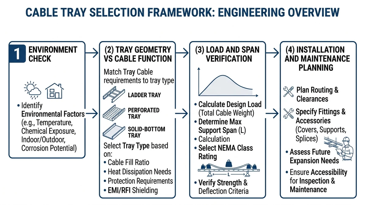
4-Step Framework to Choose the Right Cable Tray Type
Use this 4-step framework to choose a cable tray type that meets load, environment, and maintenance needs without overspecifying. Fix your design envelope (load, span, environment), then filter options to avoid both under-designed trays and unnecessary upgrades to heavy-duty systems.
Step 1 – Define Load and Span
Quantify working load (kg/m) and maximum span (m). For example, a 300 mm wide tray carrying 45 kg/m over a 3.0 m span typically needs a light‑ or medium‑duty ladder tray per IEC 61537 load classes. If loads exceed roughly 75 kg/m, short-list ladder or solid-bottom tray and generally exclude wire mesh.
Step 2 – Map Environment and Protection
Classify indoor/outdoor, corrosion level, and any washdown, fire, or EMC requirements. Outdoor coastal routes or chemical halls usually rule out plain pre-galvanized steel. Where you need IP-like containment or falling-object protection, favor solid or perforated trays; in dry technical rooms, open ladder or wire tray may be acceptable.
Step 3 – Decide Access and Routing Style
High-change routes (control, ICT) benefit from ladder or wire mesh trays for quick drops, rerouting, and additions. Power backbones with limited change tend to favor solid or perforated trays for better mechanical protection and easier segregation between power and signals.
Step 4 – Check Compatibility and Standards
Confirm fittings, supports, and fire-stopping details exist for the chosen tray type and width (for example, 400 mm at 2.5 m span). Verify compliance with IEC 61537 or NEMA VE 1 and recalculate support spacing, fill ratio, and ampacity derating based on the final tray, material, and cover configuration.
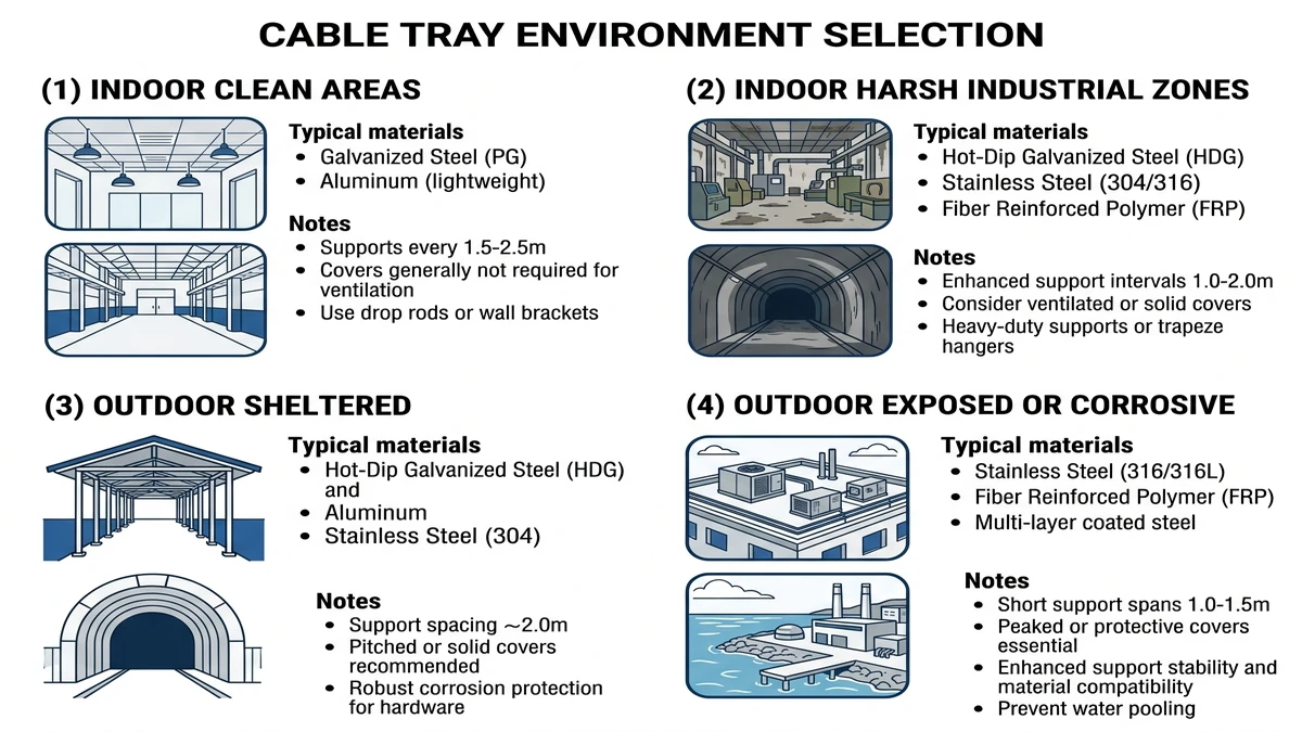
Step 1 – Use the Installation Environment to Narrow Options
Use the installation environment to eliminate unsuitable cable tray types before checking fill, cost, or fittings. Most selection errors come from underestimating corrosion, exposure, or cleanliness rather than miscalculating load.
1. Indoor vs Outdoor Exposure
In mostly dry, indoor, conditioned spaces (20–30 °C, low dust), ladder, perforated, solid-bottom, and wire mesh trays are generally possible. In outdoor or semi-outdoor routes (–20 to +45 °C, rain, UV), favor ladder or solid/perforated trays in hot‑dip galvanized or aluminum, and avoid bare wire mesh unless you add UV‑stable coating and covers.
Outdoors, ladder trays suit long runs and handle drainage, snow, and ice better than solid trays, while wire mesh should usually be reserved for indoor or protected ceiling voids with light loads.
2. Corrosion Class and Chemical Exposure
Classify corrosion roughly as low (clean offices, IT), medium (light industrial, parking decks, occasional wash-down), or high (wastewater, coastal ≤5 km from sea, chemical plant, offshore). Medium environments usually call for hot‑dip galvanized steel (zinc ≥70 µm) over thin pre-galv, and high environments often require stainless steel (304/316) or GRP/FRP trays.
If weekly wash-downs or acidic vapors (pH < 5) are expected, treat the area as high corrosion even if it is technically “indoor” and avoid thin wire systems or light coatings.
3. Cleanliness, Hygiene, and Dust
In food, pharma, and clean rooms, minimize horizontal ledges that trap dust: favor ladder or smooth-bottom perforated trays with low side flanges (≤50 mm), and avoid deep solid trays or complex wire mesh that are hard to clean. In heavy dust areas (cement, mining), open ladder trays with covers are usually easier to keep clear than solid trays that accumulate dust.
4. Fire, Smoke, and Escape Routes
Where trays pass through escape routes, high-occupancy areas, or fire-rated partitions, check local requirements for fire resistance, limits on combustible components, and fire barriers or wraps. In escape corridors, avoid GRP/FRP unless specifically tested and certified, and prioritize metallic ladder or perforated trays that can integrate cable fire-protection systems and tested fire-stopping details.
5. Mechanical Risk: Impact, Vandalism, Traffic
Below about 2.5 m or near walkways, expect incidental impact from tools and ladders and favor ladder or perforated trays with adequately thick side rails; avoid exposed wire mesh that can deform and pinch cable jackets. Over roadways and under pipe racks, anticipate wind uplift, snow, and ice and use heavier ladder systems with reduced support spacing (for example, 2.0 m rather than 3.0 m).
Quick Environment Screening Checklist
For each route, define: indoor/outdoor, corrosion level, cleanliness, fire sensitivity, and mechanical risk. If the route is outdoor or corrosion is medium–high, short-list metallic ladder or FRP and drop light wire mesh; if hygiene or heavy dust dominates, prefer ladder or perforated trays with simple profiles; if escape routes or high mechanical risk are present, prioritize metallic systems with tested fire and impact details.
Use this simple environmental line item per route to trim the tray options before starting structural and cable-fill calculations.
Step 2 – Match Tray Geometry to Cable Function and Protection Needs
Tray geometry sets cable support spacing, heat dissipation, debris protection, and modification ease. Treat selection as a trade‑off between accessibility, protection, and ampacity, and match geometry to the dominant cable function on each route.
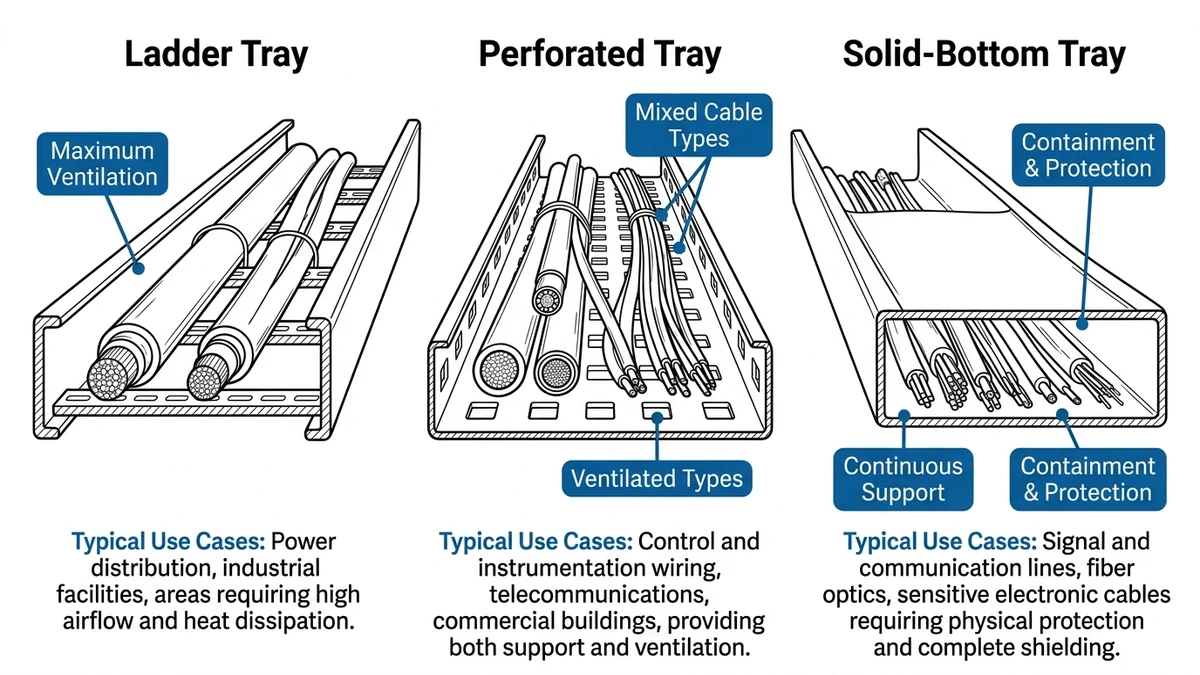
Common Tray Geometries and When to Use Them
Ladder Cable Tray
Ladder trays use side rails with rungs at 150–300 mm spacing and are common in widths of 200–600 mm. Their large open area gives strong ventilation and low ampacity derating, while frequent support points control bending radius and transfer fault forces into the side rails.
They are well suited to high-current feeders, long outdoor runs, and heavier loads (often 75–200 kg/m) and are usually the first choice for main LV and MV power routes. Avoid relying on ladder trays alone for very small singles or bare fiber unless you add support accessories or secondary containment.
Perforated Cable Tray
Perforated trays have a vented base (about 20–40 % open area) with sheet thickness typically 1.5–2.5 mm and are often used for mixed control, signal, and lighter power loads. The perforations keep most small debris out while allowing some convective cooling, and the near-continuous base distributes pressure better on small cables than ladder rungs.
They work well where loads are modest and some debris protection is needed but should be used cautiously for bulk heavy power where heat rise margins are tight or load classes become limiting.
Solid-Bottom Cable Tray
Solid-bottom trays have a continuous base and are often used at higher fill ratios (up to about 50–60 % of area) for instrumentation, low-level analog signals, and fiber. With no ventilation holes, heat escapes mainly through the metal and edges, so they incur the highest ampacity derating among tray types.
When bonded and covered, solid trays provide useful EMC shielding and good control of dust or fluid leakage, so use them where cleanliness or signal integrity outweighs thermal margin; avoid them where cables already run near temperature limits or large future load increases are likely.
Wire Mesh (Basket) Tray
Wire mesh trays are made from welded wires (often 4–6 mm diameter with about 50×100 mm grid) and are best for short, flexible routing in IT rooms and above racks, with frequent moves, adds, and changes. Their open structure gives good thermal behavior for small cables but produces higher local jacket pressure and offers limited mechanical protection.
Use wire mesh when loads are light (commonly below 25–30 kg/m), rerouting is frequent, and mechanical risk is low; for heavy power, outdoor runs without covers, or high impact risk zones, wire mesh is usually unsuitable.
Matching Geometry to Protection Needs
For each run, define the dominant cable type, environmental aggressiveness, and expected frequency of changes, then match geometry accordingly. For example, a 400 V 4×240 mm² feeder on a 15 m outdoor run belongs in a ladder or heavy perforated tray 400–600 mm wide with rung spacing ≤300 mm, while low-level 4–20 mA signals in a dusty process area often justify solid or perforated tray with covers despite the higher ampacity derating.
[Expert Insight]
– In multi-level racks, power is often placed on ladder trays at the top and signals on solid or perforated trays below to reduce EMI coupling and accidental cross-connection.
– In IEC 61537 testing, moving from perforated to ladder tray at similar gauge can often add about 0.5–1.0 m of usable span before hitting the same L/200 deflection limit, allowing fewer supports.
Step 3 – Check Load Capacity, Span, and Support Strategy
Your chosen tray type only works if its load rating and support scheme match the actual cable weight and span. Evaluate load (kg/m), span (m), and support configuration together rather than independently.
1. Estimate Realistic Tray Loading
Make a simple load estimate per meter: fully filled 300 mm power trays commonly weigh in the 5–15 kg/m range depending on cable sizes, and 300 mm control/ICT mesh trays might be around 2–6 kg/m. Add at least 20–30 % reserve for future circuits and accessories, so a calculated 40 kg/m route is reasonably designed for about 50–55 kg/m.
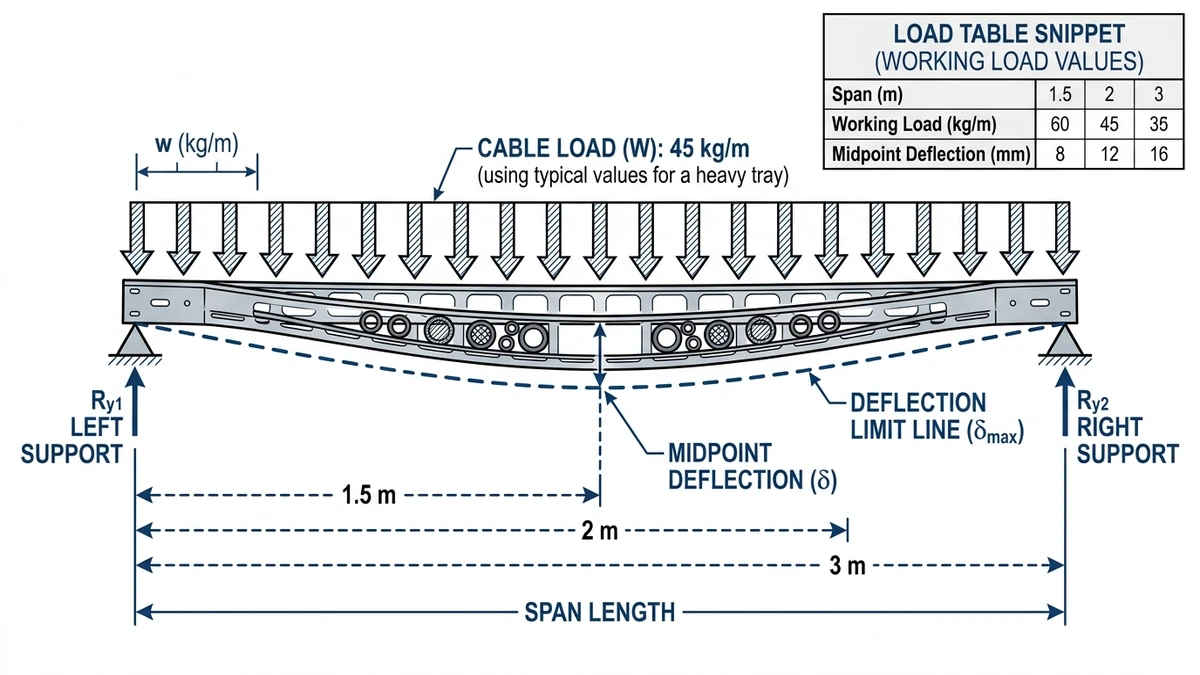
2. Match Load Class to Span
IEC 61537 ratings link allowable load to a test span (often 1.5, 2.0, or 3.0 m) and a deflection limit such as L/200. A catalog rating like “150 kg/m at 2 m span” assumes uniformly distributed load on 2 m supports; stretching this span to 3 m without recalculating can exceed allowable stress and deflection.
Typical ranges are 1.5–2.0 m spans and ≤50 kg/m for light office/ICT trays, 2.0–3.0 m spans and around 75–200 kg/m for industrial power ladders depending on material, and shorter spans (often 1.5–2.0 m) where covers, snow, or seismic loads apply even if catalog spans look higher.
3. Choose a Support Strategy That Fits the Environment
Select supports that match tray width, loading, and structural conditions: wall brackets at 1.5–2.0 m suit trays up to about 300 mm and moderate loads; hanger rods at 2.0–3.0 m are typical for 400–600 mm ladders; trapeze or framed supports are used for heavy cables, vertical transitions, or seismic bracing.
Field experience shows that stretching supports for 600 mm trays to 3.0 m and later adding cables often causes noticeable but technically “acceptable” sag, which collects water under covers and complicates access. If you push loads higher, spans longer, or supports lighter, compensate by strengthening the other parameters or reducing spacing.
[Expert Insight]
– In seismic zones, reducing spans by about 0.5 m and using braced trapeze supports tends to keep dynamic deflection and cable pullout risk under control without changing tray type.
– When suspending junction boxes of around 20 kg or more from trays, many designers treat them as equivalent to 2–3 m of extra cable during checks to avoid localized rail overstress.
Step 4 – Plan for Installation, Maintenance, and Future Changes
Cable tray selection should reflect how systems will be installed, accessed, and modified over decades. Considering installation and maintenance early helps avoid rework and reduces lifecycle cost.
Installation Constraints: Space, Supports, and Labor
Route geometry and support options strongly influence practical tray choice. In congested ceilings with only 250–300 mm free height, shallow wire mesh or channel trays are easier to handle than deep ladder sections. For long spans or when junction boxes and instruments (e.g., 20–40 kg) hang from the tray, ladder trays with higher load class per IEC 61537/NEMA VE 1 are often more robust.
Where routes have many changes in direction, penetrations, or firestops, confirm that the chosen tray system includes standard bends, tees, reducers, and risers so installers are not forced into extensive field fabrication.
Maintenance and Inspection Access
Decide how often routes must be opened and inspected. Open ladder or wire trays allow quick visual checks and simple cable work from below, which suits control and instrumentation circuits that receive periodic intervention. Solid-bottom trays with covers can improve cleanliness in dusty or hygienic plants but require removing covers for even minor tasks, adding time and sometimes extra access equipment.
In areas served only by ladders or narrow platforms, trays that demand tool removal of many cover sections significantly increase maintenance hours across a facility.
Planning for Future Cable Additions and Changes
Most installations evolve, so plan for additions. Designing trays with about 40–50 % fill at commissioning usually leaves space for new circuits without triggering major mechanical or ampacity rework; beyond roughly 60 % fill, even one extra large power cable can require redesign. Ladder and wire trays simplify adding cables over longer runs, while solid-bottom trays with many direction changes make later work more disruptive.
Where future segregation (such as adding data) is likely, choose tray families that accept dividers and covers on the same base width so you can reconfigure without replacing the support steel.
How Xinma Helps Coordinate Tray Type, Loading, and Support Details
Tray type, loading, and support design are closely coupled. Switching from wire tray to ladder can change feasible spans (for example, 1.5 m to 2.5 m), while adding covers may add 3–6 kg/m and alter deflection limits, and raising fill from 30 % to 60 % can push ampacity derating above roughly 15–20 % depending on geometry and grouping.
Because of these interactions, tray selection should be treated as a coordinated engineering decision rather than a simple catalog choice. At Xinma, project reviews typically cover:
Matching tray type and load class (for example, 100 kg/m vs 200 kg/m per IEC 61537) to cable weight plus covers, snow, and maintenance loads.
Verifying support spacing, hanger type, and midspan deflection for each width (200, 400, 600 mm, etc.).
Checking fittings, transitions, and bonding paths so elbows, tees, and reducers maintain structural rating and electrical continuity.
If you share a one‑line routing sketch and basic load assumptions, Xinma can suggest tray types, spans, and accessory sets as a coherent package and highlight where derating, corrosion protection, or seismic bracing affects your design.
For more detail on product families, see the overview of cable tray systems, with deeper information on ladder-type tray designs and perforated tray configurations. For projects combining trays with high-current distribution, busway solutions can be coordinated so supports, clearances, and thermal behavior align across both systems.
This page focuses on its stated search intent. For product-level selection, start from Xinma Cable Tray Systems and then compare the related engineering guides linked above.
Engineering Evidence and Verification Sources
This article has been updated with explicit source and procurement checks so engineering, EPC, and purchasing teams can verify the recommendations instead of relying only on generic product descriptions. For project use, treat the table below as a starting evidence map and confirm the final requirements against local codes, consultant drawings, and supplier submittals.
Use this source to verify standards, product scope, installation assumptions, or supplier evidence before final specification.
Buyer Verification Checklist
Request drawings that show tray width, depth, side rail profile, bend radius, fittings, and support spacing.
Ask for load tables or engineering assumptions that state test span, load class, and deflection criteria.
Confirm material grade, surface finish, coating method, and corrosion exposure assumptions before comparing prices.
Check whether accessories such as covers, couplers, reducers, clamps, grounding jumpers, and brackets are included.
For EPC or export orders, review packaging, labeling, inspection records, and drawing revision control before shipment.
Frequently Asked Questions
How do I choose between ladder and perforated cable trays for power cables?
Use ladder trays when current is high, spans are long, or outdoor exposure is significant because ventilation and structural capacity are better; use perforated trays when loads are lighter and you need some protection from small debris but still want partial cooling.
What cable tray type is best for data centers?
Data centers typically use wire mesh or shallow perforated trays above racks for patch and fiber routing, combined with ladder trays for main power feeders, so selection depends on whether the run is serving power distribution or network connectivity.
How much spare capacity should I allow in a new cable tray installation?
It is generally good practice to size trays so that initial fill is around 40–50 % of available area, which leaves room for future circuits without triggering major ampacity or structural rechecks.
Can I mix power and control cables in the same cable tray?
You can often mix power and control cables in the same tray if you maintain spacing or use metallic dividers and respect local code requirements, but for sensitive signals it is usually safer to separate into different trays or compartments to reduce electromagnetic coupling.
What span should I use for cable tray supports in industrial plants?
Industrial plant trays are commonly supported at 2.0–3.0 m spans for main ladders and 1.5–2.0 m for lighter trays, but the final span should follow the tray’s tested load class, actual cable weight, and any extra loads such as covers or snow.
Kevin Zheng
Kevin Zheng is a manager linked to Shanghai Xinma Busway & Cable Tray Co., Ltd. He writes technical content on cable tray systems, installation practice, sizing logic, load classes, and related standards for industrial and infrastructure applications.