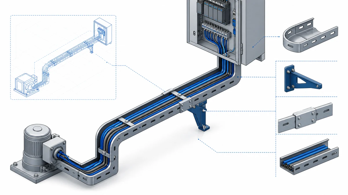
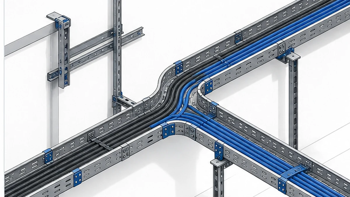
Channel cable tray is a narrow cable-support option used where a route carries a limited group of cables and the project needs an organized, accessible path. It appears frequently on instrument, control, communication, and equipment branch routes, but the product name alone does not establish the correct width, material, support arrangement, or cable capacity. Those decisions must follow the approved cable schedule, route drawings, project specification, and selected manufacturer data.
Begin with the Xinma cable tray system range. This guide does not replace the responsible engineer’s design, local installation rules, or the contract inspection plan.
What Channel Cable Tray Means in a Project Context
Channel tray is a relatively narrow formed section that creates a defined cable route. Bottom and rail profiles vary by product family. It needs the same complete-system review as any tray route: matched fittings, splices, supports, accessories, material, finish, and documented interfaces.
Do not select channel tray solely because a route looks small on a drawing. Review the cable types, quantity, cable outside dimensions, any future changes approved by the project, electrical separation needs, installation access, support points, and termination details. A route that begins as a compact control run can still require a different system if the cable schedule, routing, or maintenance conditions change before procurement is released.
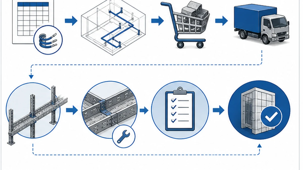
A compact route begins with the approved cable schedule.
Suitable Cable Groups and Route Constraints
Channel tray can be considered where the design calls for a compact, clearly controlled cable path and the selected product’s published data suits the actual load and span. Typical applications include equipment branches, control connections, instrumentation routes, and supporting cable paths around panels or machinery. The route must remain accessible for cable placement, identification, inspection, and future approved maintenance.
The following table summarizes common cable groups and the route-level conditions that support or limit channel tray use. Treat it as a starting checklist rather than a definitive selection rule.
Cable Group
Typical Route Characteristic
Key Constraint to Verify
Instrument signal cables
Short branch from junction box to field device
Separation from power cables per project spec
Control cables
Panel-to-panel or panel-to-device branch
Cable schedule stability; future additions
Communication cables
Equipment room or local network branch
Bend radius limits; EMI separation
Equipment branch power
Short run to a single load
Conductor size and fill ratio against product data
Fiber-optic cables
Dedicated protected route
Minimum bend radius; cover requirement
Before final selection, confirm headroom and cover clearance, support attachment points, panel or equipment entries, required segregation, and any fire-rated boundary condition.
At the design review, compare channel tray with available alternatives. A perforated cable tray system may be appropriate when the project needs a broader cable-support surface, a different fill geometry, or improved ventilation around cables. A route carrying a larger or more varied cable group may need a different tray family entirely. The correct choice follows the documented cable route rather than a generic distinction between light and heavy duty.
System Compatibility: Fittings, Covers, and Dividers
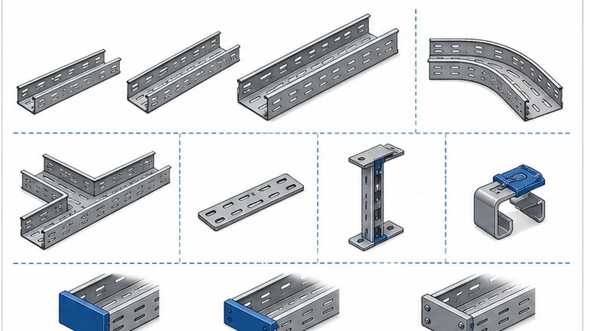
A channel tray route is only as complete as its fittings and accessories. Bends, risers, tees, reducers, splice plates, end caps, covers, clips, dividers, bonding components, and labels must match the product family and appear explicitly in the BOM.
Use the cable tray fittings range to verify that bends, reducers, and connection hardware are catalogued for the selected section profile. At a transition to a larger tray, panel, or equipment enclosure, check the tray profile, fitting orientation, cable entry direction, support position, and any required protective edge treatment. Avoid field-made transitions unless they have been explicitly engineered and approved by the responsible engineer.
Cover implications. Where a cover is required, it must match the section width and use clips or fasteners suited to the rail profile. Check seating before cable work.
Divider implications. Where separation is required, select a compatible divider. It reduces usable fill width, so confirm position, fixing, and cover compatibility before finalizing the BOM.
The BOM needs matched components, not sections alone.
Triggers for Moving to a Wider Tray Family
Several conditions should prompt a reassessment of channel tray in favor of a wider or different system. Identifying these triggers early avoids a late BOM revision or a field substitution.
Cable schedule growth. If the approved cable schedule is revised to add cables before procurement is released, recalculate the fill ratio against the selected section. If the section cannot accommodate the updated group with the required spare capacity, move to a wider product.
Segregation requirement. If the project specification requires physical separation between cable groups that cannot be achieved with a divider in the selected width, a wider section or a separate tray route is needed.
Bend radius conflict. If the route geometry requires a tight bend that the selected section’s fittings cannot achieve without violating the minimum bend radius of any cable in the group, review the fitting range or the route path.
Support span limitation. If the available support points are spaced beyond the published maximum span for the selected section under the actual cable load, either add intermediate supports or select a section with a higher published span rating.
Maintenance access. If the installed route will not allow cables to be added, removed, or inspected without removing the tray, the route geometry or the product selection should be reconsidered.
Future scope. If the project has a documented future phase that will add cables to the same route, size the tray for the final condition rather than the initial installation.
Define the Complete BOM Before Ordering
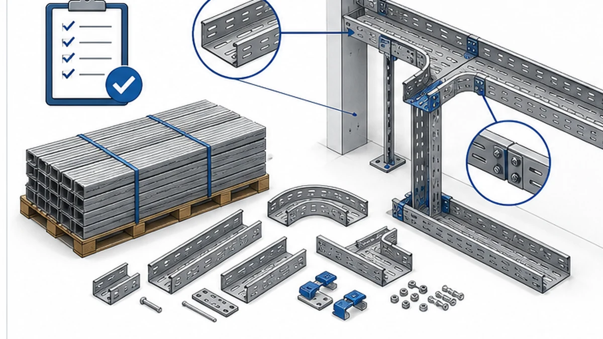
The BOM should identify the tray section, nominal dimensions, material, finish, section length, and product family. It should also list every bend, tee, reducer, riser, splice plate, support component, cover section, cover clip, divider, end treatment, bonding component, and label required by the approved route. A generic line for “small tray with accessories” is not sufficient to confirm an installable package.
[ ] Covers and dividers: codes, clips, fixing method, and compatibility with the rail profile
[ ] Support scope: brackets or trapeze parts, anchors, and structural-substrate interface
[ ] Electrical and cable-retention items: bonding components, cleats or clips, and labels where specified
[ ] Required material, finish, and delivery records
Support hardware must also match the approved design. The cable tray support guide helps teams check available structure, support geometry, installation access, and published product data. The responsible engineer determines the actual support arrangement, anchors, cable load case, and any project-specific restraint. Procurement should confirm that approved support items appear as explicit order lines rather than being assumed as site consumables.
Material, Finish, and Interface Verification
Material and finish are selected against the documented project environment, corrosion strategy, maintenance plan, and manufacturer data. Labels such as “indoor,” “outdoor,” or “industrial” are not complete material instructions. State the selected requirement in the approved purchase documents, together with any required material or finish records.
At interfaces, confirm the selected tray can connect to the intended supports, enclosures, cable entries, and adjacent tray systems. If a route needs a divider, cover, bonding component, restraint, or special edge protection, include the compatible parts in the BOM and identify the governing project requirement. Do not assume that a narrow tray section automatically provides electrical separation, grounding continuity, physical protection, or any enclosure performance.
For system-performance context, refer to the direct IEC 61537 publication. It does not establish a universal channel-tray sizing or installation rule. Verify every design-critical requirement with the project documents and the selected manufacturer’s data.
Trial fitting protects against interface mistakes.
First-Install Inspection Workflow
The following workflow applies to the initial installation of a channel tray route. It is a field-coordination aid, not a substitute for the approved project method statement or inspection and test plan.
Step 1 — Goods receipt. Compare part numbers, dimensions, finish, fittings, hardware, condition, and documents with the controlled BOM using the project sampling method.
Step 2 — Trial fit. Fit a representative tray-to-splice joint, cover and clip, and support bracket. Confirm seating and prevent product-family substitutions.
Step 3 — Route confirmation. Check support locations, attachment points, clearances, and drawing deviations before erection; refer deviations for engineering review.
Step 4 — Installation and cable check. Follow the method statement, verify joints and fitting orientation, then confirm protected entries, fill against the cable schedule, covers, and labels before handover.
Step 5 — Handover. Retain the approved route, authorized changes, material records, inspection results, and support/fitting arrangement. Recheck the route when later cable changes are proposed.
The cable tray installation guide can help organize the field sequence, but the approved project method statement controls the installation. Any routing or cable-schedule change should be reviewed for its effect on the tray selection, fittings, supports, and remaining material quantities.
Controlled records preserve the installed route.
Xinma Ecosystem Considerations for Channel Tray Routes
Xinma supplies channel tray with compatible fittings, covers, dividers, support brackets, and bonding accessories. Confirm that the selected width has matching fittings in the specified material and finish, that clips suit the actual rail profile, and that bracket geometry suits the structure. At a busway or larger-tray interface, check the fitting, cable entry, and support position against both product families before BOM release. For seismic zones, review compatible restraint hardware against the approved design. Receiving checks should match product codes, clip seating, and splice-hole alignment to the approved BOM; phased deliveries should retain the original codes to avoid profile or finish mismatches.
Frequently Asked Questions
What types of cable runs are suitable for channel cable tray?
Channel tray can be considered for compact routes such as control, instrumentation, communication, or equipment branches where the approved cable schedule, route geometry, support design, and selected product data support that choice. The suitability of any specific route must be confirmed against the actual cables, fill ratio, span, and project specification rather than assumed from the route description alone.
How is channel tray different from a wider cable tray system?
Channel tray is normally used for a more compact route carrying a limited cable group. The correct system is determined by the actual cables, route conditions, supports, fittings, access, segregation requirements, and project specification, not a fixed size threshold. When the cable schedule grows or the route conditions change, a wider or different system may be required.
Should channel tray fittings be ordered separately?
Every fitting, splice plate, support part, cover section, cover clip, divider, and connection item should appear as an explicit BOM line or as an explicitly listed item in a confirmed supply package. Do not assume that fittings or accessories are included with straight sections. Confirm each item against the approved route drawing before releasing the order.
What should be checked before accepting a channel tray delivery?
Compare part numbers, nominal dimensions, material or finish identification, fittings, hardware quantities, visible condition, packing information, and required records against the approved order and inspection plan. Perform a trial fit of a representative joint, including cover and cover clip, before accepting the batch for erection.
When should a small cable route be reviewed for a different tray type?
Review the selection when the cable schedule, route geometry, maintenance access, support conditions, segregation requirement, or future approved scope changes. Reassess the fill ratio, span, fitting availability, and cover and divider compatibility against the selected manufacturer’s data and the approved project design before proceeding with procurement or installation.
Kevin Zheng
Kevin Zheng is a manager linked to Shanghai Xinma Busway & Cable Tray Co., Ltd. He writes technical content on cable tray systems, installation practice, sizing logic, load classes, and related standards for industrial and infrastructure applications.