Precise terminology matters when drawings, RFQs, submittals, BOMs, and inspection records must describe the same item. A familiar term can still mean a different product family, interface, or contractual responsibility. This glossary gives engineers, procurement teams, and inspectors a shared cable-tray vocabulary by document stage and product category.
These definitions do not replace the contract specification, local code, or the responsible engineer’s system selection. Use them with the Xinma cable tray system range, approved drawings, and project data.
Term-to-Document Reference Matrix
The table maps term categories to documents where precise use is most critical. Blank cells indicate lower ambiguity, not irrelevance.
Term Category
RFQ
Submittal
Drawing
BOM
Inspection
Tray type and geometry
Primary
Confirm
Primary
Primary
Verify
Fittings
Primary
Confirm
Primary
Primary
Verify
Supports and anchors
Primary
Confirm
Primary
Secondary
Verify
Covers and dividers
Secondary
Confirm
Secondary
Primary
Verify
Splice plates and hardware
Secondary
Confirm
Secondary
Primary
Verify
Material and finish
Primary
Primary
Secondary
Primary
Primary
Bonding and continuity
Secondary
Secondary
Primary
Secondary
Verify
Seismic restraint
Primary
Confirm
Primary
Secondary
Verify
System terms connect the drawing to the installed route.
System-Level Terms
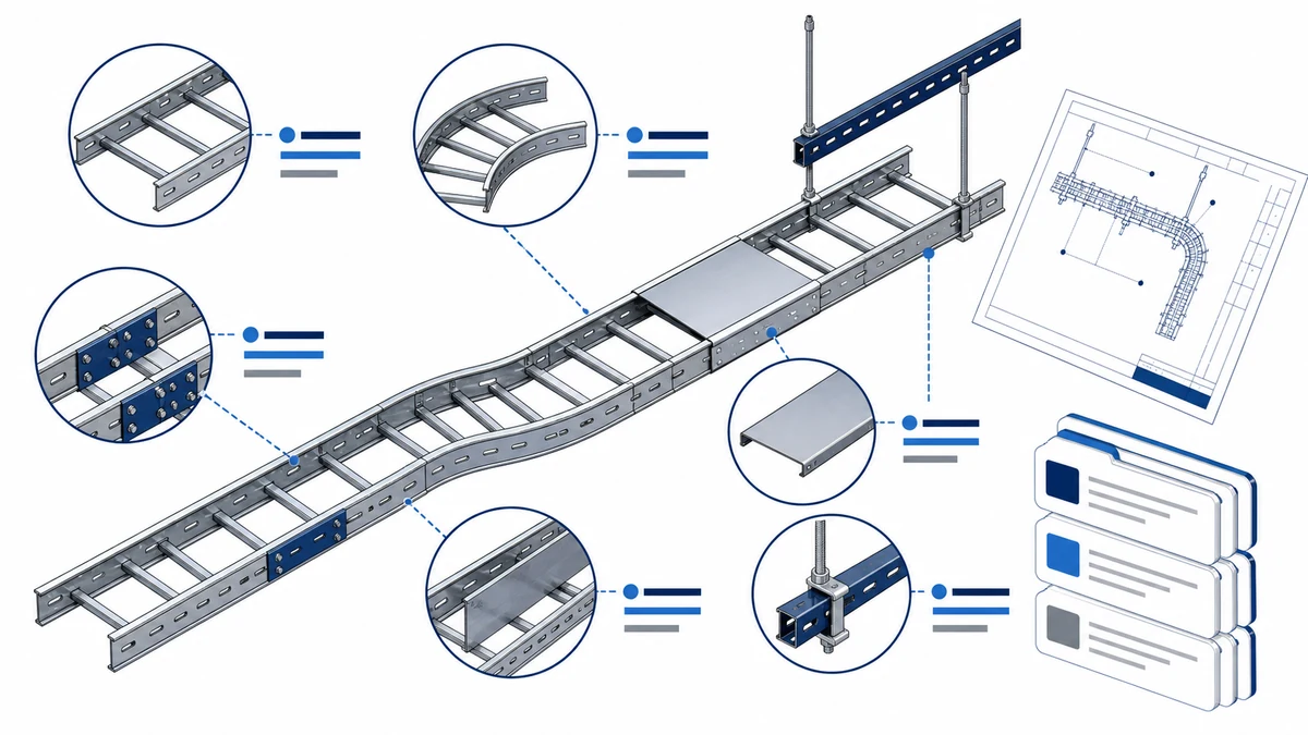
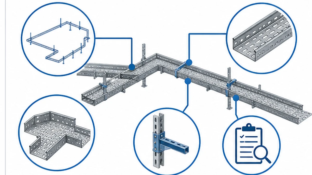
Cable tray system means the connected route assembly made up of tray sections, fittings, supports, connection hardware, and specified accessories. The system must be reviewed as an assembly. A tray section cannot be evaluated independently from the fitting, support, and connection conditions shown on the approved design.
Tray section is a straight manufactured unit that forms part of a route. Its description normally includes tray type, nominal width, side-rail depth, material, finish, section length, and connection method. Usable geometry and available lengths come from the selected manufacturer and project documents, not from a nominal label alone.
Continuous run describes connected tray sections and fittings forming one routing path. It may pass through several zones and requires coordinated supports, connection hardware, and inspection hold points.
Cable management system is the broader term for cable tray, conduit, cable duct, busway, and other routing methods. A purchase order must still identify the exact product family for each route segment.
Nominal width and side-rail depth describe route geometry. The engineer selects them from cable data, separation, the approved method, supports, and manufacturer data. Do not assume that matching nominal dimensions have matching usable geometry or connection profiles.
Tray Types and Route Geometry
Ladder cable tray has two side rails joined by transverse rungs. It may suit routes needing an open support structure and direct cable access. Rung pitch, rail profile, load data, and fitting interfaces are product-family characteristics. See the ladder cable tray product reference for family-specific data.
Perforated cable tray has a formed bottom with openings. Perforation pattern, material, finish, and accessory compatibility vary by product line. It may suit a design needing more continuous support while retaining openings.
Solid-bottom cable tray has a continuous bottom surface. The project team must still confirm access, drainage, thermal, cover, and cable-protection requirements.
Trough describes a deep-sided, solid-bottom section where containment or protection depth is specified. Confirm side-rail height, bottom profile, and fitting compatibility before listing it in the BOM.
Channel tray (also called wire basket or cable basket) is a lighter-duty, open-wire or formed-channel system. It is not interchangeable with ladder or perforated tray in structural or fitting terms. Use its product-family name on the RFQ.
Span is the support distance in the approved design. It derives from cable load, route geometry, structure, and selected-tray data. A catalogue value does not replace the project support design.
Fittings, splice hardware, covers, and dividers have distinct procurement and inspection responsibilities. A single “accessories included” BOM line creates scope gaps.
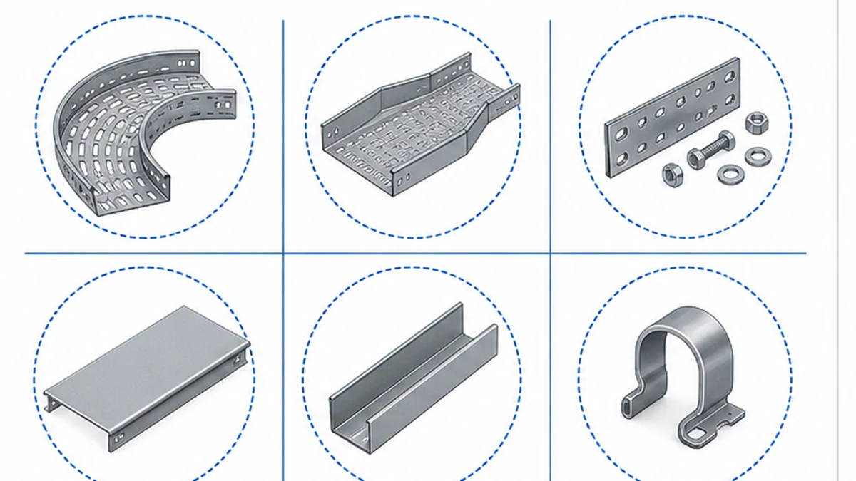
Fittings change direction, level, or width along a route. Common types include horizontal bends, vertical bends (inside and outside), tees, crosses, reducers, and risers. Each fitting must match the adjacent tray family’s width, depth, rail profile, material, and finish. Refer to the cable tray fittings range for product-family interface data.
Splice plate connects adjacent tray sections and performs the selected system’s mechanical joint function. Do not assume it also provides electrical continuity or thermal movement. Product data and the electrical design define any bonding, expansion hardware, or testing.
Reducer is a fitting for a tray-width transition. Show it on the route drawing, not as a percentage allowance. Verify cable arrangement, direction, support position, and adjacent connections at each transition.
Cover sits above a tray where the design requires exposure management, cable retention, or defined protection. Its profile, clips, fasteners, and fitting pieces must match the selected family. It does not alter tray load rating unless manufacturer data says so.
Divider separates cable groups when the electrical design requires segregation. Check its height, longitudinal parts, and fitting behavior against the selected accessory family. Confirm continuity through bends and tees before finalizing the BOM.
Bonding jumper establishes continuity across a joint, fitting, or expansion point where a splice plate does not provide a defined path. The electrical design states when it is required and what test applies; a glossary cannot do so.
Support and Structural Terms
Support transfers tray and cable load to the building structure through wall brackets, trapeze frames, cantilevers, or other approved configurations. The cable tray support guide is a route-to-support check, but spacing, anchors, and capacity remain project-specific engineering decisions.
Trapeze frame is a suspended support assembly using threaded rod, a crossbar, and tray clamps. Rod diameter, crossbar profile, clamps, and the structure connection must be specified separately. “Trapeze support” is not a complete BOM description.
Wall bracket is a cantilevered support fixed to a vertical structure. Bracket projection, tray-seat width, fixing pattern, and load capacity must match the route geometry and approved structural assessment.
Anchor is the approved connection between a support assembly and the building structure. Its suitability depends on the base material, approved load case, installation method, and required inspection hold point. Anchor selection cannot be derived from tray width alone.
Seismic restraint is a project-specific lateral or longitudinal restraint arrangement required where the applicable design standard calls for it. It is separate from ordinary vertical support. The responsible engineer determines the scope, components, anchor types, and verification method. Do not treat seismic restraint and routine support as interchangeable BOM items.
Bonding continuity refers to the electrical arrangement required across metallic route components. The electrical design should state when continuity testing, bonding jumpers, or a particular connection method is needed at support attachment points. Do not treat a glossary definition as a commissioning acceptance criterion.
Inspection terms connect the BOM to delivered material.
Material, Finish, and Document Terms
Material describes the base product selected for the project. Steel, stainless steel, aluminum, and non-metallic systems have different structural, thermal, and corrosion characteristics. The selected material must align with the environmental classification, corrosion strategy, cable route conditions, structural requirement, and approved manufacturer data.
Finish describes the surface treatment or coating applied to the selected material. A finish name alone is not a complete acceptance criterion. The purchase package should state the project requirement, applicable test or documentation standard, and inspection method rather than relying on a generic assumption about indoor, outdoor, chemical, or coastal suitability.
Submittal is the manufacturer information provided for review before production or release. For cable tray, it may include dimensional drawings, system load data, material and finish documentation, compatibility details, and any records expressly required by the contract. A submittal is an input to engineering approval, not a replacement for the engineer’s design decisions.
Bill of materials (BOM) lists every tray section, fitting, support component, cover, divider, splice plate, bonding jumper, and accessory required for the route. A BOM that uses vague descriptions such as “fittings as required” or “accessories included” creates scope gaps that surface during delivery verification or site installation.
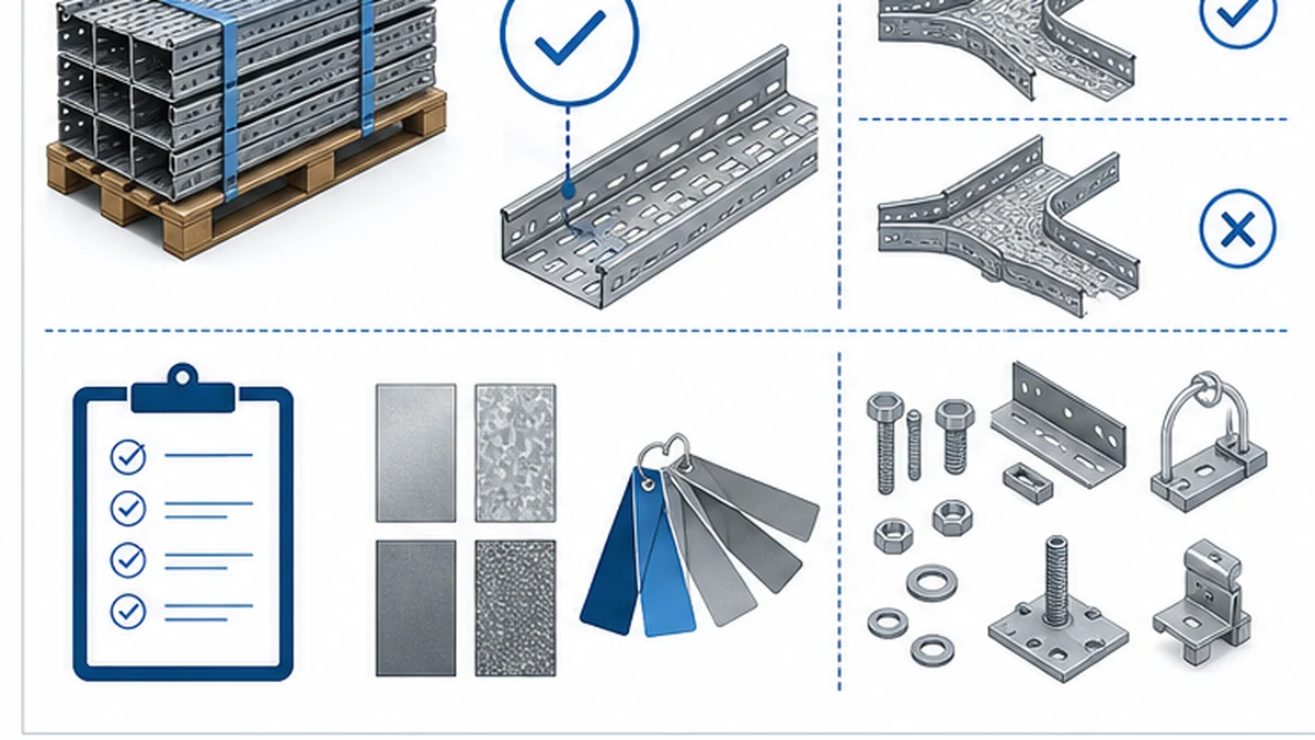
Inspection and test plan (ITP) sets the project-specific checks, hold points, responsibilities, and records. Incoming inspection can compare part numbers, dimensions, finish identification, fitting orientation, hardware quantities, visible damage, and packing information against the approved order. The ITP, not this glossary, determines the sampling method and acceptance criteria.
For system-performance context and classification requirements, refer to the direct IEC 61537 publication.
Procurement Clarification Workflow
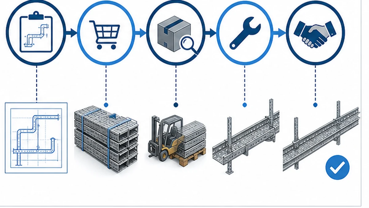
When an RFQ or purchase order returns for clarification, the cause is usually a term that was interpreted differently by the engineer, the supplier, and the site team. The workflow below identifies the most common checkpoints.
Step 1 — Align terms across documents before issue. Confirm that the tray type name, fitting descriptions, support scope, material, and finish use identical language in the specification, the drawing title block, and the BOM. Discrepancies between documents are the most frequent source of RFQ queries.
Step 2 — Separate scope boundaries explicitly. Define whether support hardware, anchors, seismic restraints, bonding jumpers, covers, and dividers are in the tray supplier’s scope or another package. “Support by others” is not sufficient when the tray clamp, rod, and anchor each belong to different supply boundaries.
Step 3 — Require submittal before production release. The submittal review should confirm dimensional compatibility between tray sections, fittings, covers, dividers, and supports. Identify any fitting that requires a non-standard interface or a project-specific fabrication.
Step 4 — Use the ITP at goods receipt. Check delivered part numbers, finish, fitting orientation, hardware quantities, and documents against the BOM. Use the cable tray installation guide with the project method statement before installation, and record discrepancies before site distribution.
Step 5 — Resolve changes through a formal revision. Any change to tray width, material, finish, or fitting type after submittal approval requires a BOM revision, a drawing update, and a re-check of support spacing and bonding continuity requirements.
Consistent terminology supports each project handoff.
Xinma Ecosystem Considerations
Xinma supplies cable tray sections with compatible fittings, covers, dividers, splice hardware, bonding accessories, busway systems, and seismic-bracing components. A coordinated product family lets teams compare model codes, finishes, clamp interfaces, and BOM lines against one data set. For busway transitions or seismic-bracing routes, specify interface hardware and restraint geometry in the package rather than resolving them on site. Receiving checks should match covers, dividers, and bonding jumpers to approved submittal part numbers. Load, anchor, and continuity decisions remain with the project team.
Frequently Asked Questions
Is cable tray the same as cable duct?
No. The terms are sometimes used interchangeably in informal conversation, but a technical purchase order must identify the required product family and route function. Cable tray, conduit, and enclosed duct systems have different route characteristics, access requirements, and protection levels. Using the wrong term on an RFQ can result in a quotation for an incompatible product family.
What should a cable tray fitting description include on a BOM?
A fitting line item should state the fitting type, the adjacent tray family name, nominal width on each leg, side-rail depth, material, finish, route orientation, and any required connection hardware or bonding components. The approved drawing and selected manufacturer data provide the final part identification. A description that states only “90-degree bend” without the remaining attributes is insufficient for procurement or inspection purposes.
Does a splice plate automatically provide grounding continuity across a joint?
Do not assume so. The electrical design and selected system documentation define the required continuity arrangement, any supplementary bonding components, and the applicable test method. Some splice plate configurations provide a defined continuity path; others require a bonding jumper in addition to the mechanical splice. Confirm the requirement in the project electrical design before finalizing the BOM.
Why must a purchase order use the same terminology as the approved drawings?
Consistent terminology allows procurement, the supplier, and site inspectors to compare the same tray section, fitting, accessory, or support scope against a single reference. When a purchase order uses a different term than the drawing, the supplier may quote a different product, and the receiving inspector may accept a non-conforming item because the description appeared to match. Alignment across documents is a basic scope-control measure.
What documents should be reviewed before accepting a cable tray delivery?
Compare the approved purchase order, BOM, drawings, packing list, required submittal records, and the project ITP. Confirm that delivered part numbers, finish identification, fitting orientation, hardware quantities, and visible condition match the approved scope before items are distributed around site. Discrepancies found after distribution are significantly more difficult to resolve than those identified at the point of receipt.
Kevin Zheng
Kevin Zheng is a manager linked to Shanghai Xinma Busway & Cable Tray Co., Ltd. He writes technical content on cable tray systems, installation practice, sizing logic, load classes, and related standards for industrial and infrastructure applications.