Quick Answer: What Cable Tray Systems Are Used For in Industrial and Commercial Buildings
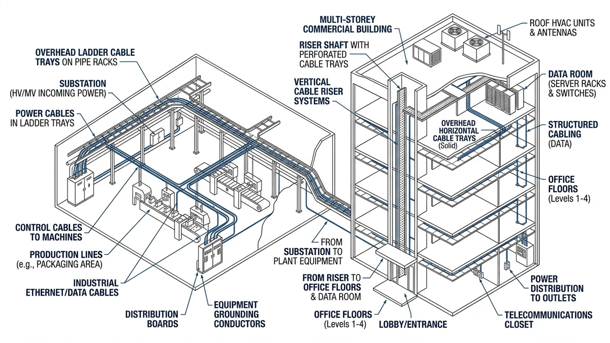
Cable tray systems in industrial and commercial buildings are used to route, support, and protect low‑voltage power, control, and data cables over typical spans of 2–6 m between supports. They replace or reduce conduit runs, manage high cable densities (often 20–40 kg/m), and keep circuits accessible for inspection, additions, and fault repair while maintaining thermal limits and segregation rules.
Key Functions: Support, Routing, Protection, and Thermal Behavior
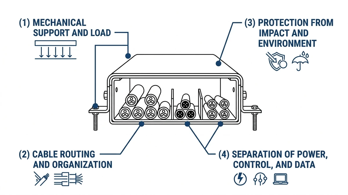
Cable tray systems in the field do four things at once: they carry cable weight, define routing, provide mechanical/environmental protection, and influence cable operating temperature. Every tray choice affects at least two of these functions.
Figure 1. Project-relevant comparison visual aligned with the article?s main decision point.
Structural Support Under Real Loads
IEC 61537 and NEMA VE 1 classify cable ladder and tray by allowable uniformly distributed load and maximum deflection (typically limited to L/200 or L/250), so the tray, supports, and anchors can be sized as a system.
On a 300 mm wide ladder tray spanning 3.0 m, a typical proof load is about 150 kg/m, or 450 kg per span; if your calculated cable load is 90 kg/m, utilization is 60%, meaning you can either add cables or increase span slightly, but not both without moving to a higher class. In seismic or vibration‑sensitive areas, reducing spans from 3.0 m to 2.0 m commonly cuts midspan deflection by 30–40% and reduces clamp loosening under machine vibration.
Figure 2. Standards, loading, sizing, or material reference graphic tied to the section logic.
Routing and Segregation
Cable trays create fixed corridors that control route length, voltage drop, EMC performance, and future expansion. Minimum bend radii (often 8–12× cable diameter) push designs toward factory elbows, tees, and drops instead of tight field‑bent conduit.
Two routing aspects dominate: electromagnetic segregation of power versus control/instrument cables (using ≥300 mm spacing or metallic barriers), and expansion margin by limiting tray fill to around 40–60% of internal area. On dense “highways” along pipe racks, dedicating separate ladders to power, control, and instrumentation simplifies later additions and reduces EMC issues.
Figure 3. Installation or coordination illustration showing routing, support, or maintenance implications.
Protection and Thermal Behavior
Tray type trades mechanical/environmental protection against heat dissipation. Open ladder or wire mesh trays ventilate well but offer limited protection from falling objects, UV, or liquids, while solid-bottom trays and covers protect more but restrict airflow and raise cable temperature.
Switching from ventilated ladder to solid-bottom with a solid cover can increase cable operating temperature by 5–15 °C; using IEC 60364‑5‑52 correction factors, a 240 mm² copper cable that might carry ≈360 A in free air may need to be limited to around 300 A in a tightly packed, covered tray. This is acceptable where impact, UV, or liquids are a concern (wash‑down zones, roof runs), but in hot plant rooms you may need larger conductors or fewer circuits, and always check manufacturer derating tables so ampacity still clears protective device settings.
On outdoor pipe racks, ladder tray with perforated or louvered covers is a common compromise, typically keeping ampacity penalties to about 5–10% while improving jacket protection versus fully exposed ladders.
[Expert Insight]
When you change from open ladder to covered tray late in design, always re‑check ampacity and short‑circuit withstand; extra heat shortens insulation life and can erode fault‑time margin.
In retrofits, covers are often removed and not replaced; specifying hinged or tool‑less covers in high‑maintenance areas reduces that risk.
Industrial Facilities: How Engineers Actually Use Cable Trays on the Plant Floor
On the plant floor, cable trays act as structural cable corridors between MCCs, switchgear, process skids, and field junction boxes. Route, environment, and maintenance drive choices more than catalog pictures.
Typical Power and Motor Feeder Runs
Three‑phase 400–800 V motor feeders (often 3×185 mm² and larger) typically run on ladder trays at 3–6 m elevation along pipe racks or building steel, with a main “spine” tray (300–600 mm wide) feeding branch trays down to VFDs, motors, and panels. For a 600 mm tray carrying ~60 kg/m of power cables, designers often select an IEC 61537 Class C (or higher) ladder and keep spans at 2.5–3.0 m to control deflection and dynamic movement, while in high fault‑current areas trays are bonded and routed away from escape paths to limit risk from cable failure.
Experience from high‑power compressor lines shows that reducing tray span from 3.0 m to 2.0 m and using stronger hangers can significantly cut post‑commissioning re‑tightening of cable cleats after through‑fault testing.
Segregation of Control and Instrumentation
On the same racks, smaller trays are used to keep low‑level signals away from power feeders, for example 100–200 mm perforated instrumentation trays offset ≥300 mm from power trays, with shielded cables and a dedicated earth bar for shield terminations.
Using a shared tray with a barrier minimizes material but complicates future changes and EMC troubleshooting, whereas separate trays add some cost and space demands but yield more predictable noise performance. Field experience shows fewer nuisance trips on VFD control and analog loops when power and control trays are physically separated and crossings are forced to 90°.
Harsh or High-Maintenance Zones
In dusty, wet, or corrosive zones such as wash‑downs, fertilizer plants, or marine environments, tray type and material are chosen for protection and durability: solid-bottom or perforated trays with covers for small control and instrumentation cables, and hot‑dip galvanized, aluminum, or stainless steel trays depending on corrosion class and ambient temperature.
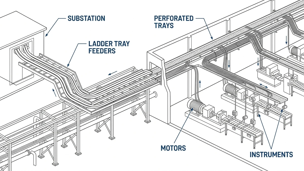
Trays are routed to maintain about 2.1 m headroom above walkways, with vertical drops consolidated at equipment edges or cable rooms so cables can be added or replaced without stepping over live circuits.
Figure 2. Industrial facility example where ladder trays carry power feeders on pipe racks and perforated trays distribute control cables above production lines.
[Expert Insight]
In high‑corrosion atmospheres, powder‑coated steel trays may pit through in under 5 years, whereas hot‑dip galvanized ladders often remain serviceable; actual corrosion class and humidity are more important than nominal coating thickness.
In wash‑down areas, drainage via perforations or weep holes and avoiding flat solid covers that trap water and chemicals significantly slows corrosion and jacket degradation.
Commercial and Critical Buildings: Tray Usage in Offices, Malls, Hospitals, and Data Centers
In commercial and critical buildings, cable trays separate power, data, and life‑safety circuits within tight space, fire, and uptime constraints. Tray type, height, and support spacing vary across offices, malls, hospitals, and data centers.
Offices and Mixed-Use Towers
In office towers, trays run mainly in ceiling voids (≈2.7–3.2 m above floor) alongside ductwork and sprinklers, typically using 150–300 mm ladder or wire mesh trays for 230/400 V power and structured cabling.
Fill is often limited to 40–50% to support tenant churn, with support spacing of 1.5–2.4 m adjusted around beams and ducts. Wire mesh suits frequent small‑cable changes where impact risk is low, ladder or perforated trays are preferred above public areas, and solid covers are avoided unless required by fire or plenum rules because they can raise cable temperatures by several degrees.
Shopping Malls and Public Venues
In malls, long concourses and high ceilings drive designs with 400–600 mm trunk trays suspended at 4–6 m for tenant feeds, signage, and small equipment, and with covers or transitions to conduit wherever trays pass above escalators, atriums, or dense public areas.
Partitioned trays or dual runs often separate landlord distribution from tenant submains to simplify metering and later fit‑outs. Longer spans between roof trusses (3–4 m) usually require heavier load‑class trays and deflection checks, and in seismic regions lateral bracing is added to prevent trays swinging into sprinkler mains or glazing.
Hospitals and Healthcare Facilities
Hospitals require essential power systems and strict segregation to protect clinical equipment, so designers specify dedicated trays for life‑safety loads, medical IT, and normal power, often color‑coded and spaced ≥300 mm apart, with riser trays feeding critical areas and fire‑stopping at each floor.
Wire mesh is used sparingly near sensitive imaging or diagnostic equipment; ladder or solid‑bottom trays with defined bonding points are preferred to control EMI. Over hospital corridors, multiple tray tiers can push cumulative loads to 40–80 kg/m, so the support frames and anchors are checked as a single assembly to avoid overloading the structure.
Data Centers and Mission-Critical Facilities
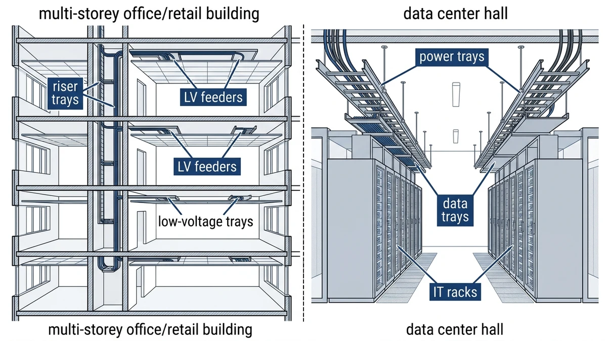
In data centers, tray layout affects both uptime and airflow. Overhead ladder trays 600–900 mm wide carry server power whips at about 3.0–3.6 m above the raised floor, with separate, independently supported A and B tray systems spaced 600–1,000 mm apart to maintain redundancy.
High‑density low‑voltage trays or wire baskets carry fiber and copper, usually routed orthogonally to power to reduce crosstalk. Grouping several power trays above hot aisles can raise local ambient temperature by 5–10 °C, so designers often derate ampacity by 10–20% or increase tray spacing, and limit stacking to 2–3 tiers so live work and circuit tracing remain manageable.
Figure 3. Sectional view of a commercial tower and data hall with cable tray routes in risers, above ceilings, and over IT racks.
Coordinating Cable Trays with Busway and Other Systems
Cable trays share space with busway, ductwork, and structural steel, so early coordination reduces clashes and rework.
When to Use Tray vs. Busway
High‑current distribution in industrial plants and large commercial buildings is often handled by busway, with cable trays serving downstream feeders and controls.
Busway provides defined short‑circuit ratings and low impedance for efficient 1,000–6,300 A distribution, while cable tray is better for multiple smaller feeders, motor circuits, and controls with frequent changes. Use busway for straight, high‑capacity risers or mains with continuous support and tap‑off needs, and use tray where routes are irregular, loads diverse, or flexibility is critical, always checking structural support lines, short‑circuit levels, and expansion requirements.
Aligning busway routes with main tray “highways” simplifies tap‑off cable runs and tray sizing.
Applying These Uses to a Real Specification with Xinma
Across real projects, cable tray selection is usually fixed early in terms of allowable loading (e.g., 100–200 kg/m), maintenance access strategy, and support span (often 2.0–3.0 m indoors and 1.5–2.0 m outdoors). Xinma’s tested data and catalog ranges are relevant where these interact.
Turning Field Conditions into Tray Choices
From the use‑cases above, several practical consequences follow:
Covers and ventilation
Adding solid covers and switching from ladder to solid‑bottom increases mass and reduces ventilation; allowable span may drop by about 0.5 m and ampacity may need 5–15% derating depending on cable fill.
Covers are best reserved for routes exposed to mechanical damage, liquids, or falling debris, and generally avoided in hot or crowded ceiling spaces unless required by fire or hygiene rules.
Tray width and mixed circuits
Wider trays (≥600 mm) carrying mixed power and control circuits are less stiff and have higher thermal mass, so spans are often limited to about 1.5–2.0 m to keep deflection under L/200, especially when fill exceeds 50%.
In EMC‑sensitive applications, two narrower trays with segregation usually perform better than one wide mixed tray.
Outdoor and corrosive routes
Outdoor, high‑temperature, or corrosive routes often require heavier ladder trays with thicker side rails, corrosion‑resistant materials, and closer supports (1.5–2.0 m spacing).
Snow, ice, and wind loads must be considered; snow/ice can add 10–20 kg/m or more to the design loading in some climates.
Treating the Tray System as an Engineered Assembly
Because loading, access, and support interact, tray width and material cannot be chosen in isolation. In coordinated designs it is standard practice to:
Confirm cable weight (kg/m) including future allowance, covers, and environmental loads against the tray’s tested load class.
Check support spacing and hanger configuration against span tables and deflection criteria.
Verify that fittings—bends, tees, reducers—respect minimum bend radii and do not introduce weak points.
Apply thermal derating for tray type, grouping, and ambient temperature, then confirm protective devices still operate correctly.
Using manufacturer‑tested data rather than generic assumptions reduces the risk of overstressed runs or unexpected derating during commissioning.
Instead of a single generic line in the specification, treat cable tray as a system coordinated with cables, supports, and building structure. Xinma’s engineering team can:
Review one‑line diagrams, preliminary cable schedules, and routing sketches to propose tray types and widths suited to field constraints.
Check that chosen spans and hanger types match tested performance for the tray series and expected loading.
Flag where changes such as covers, material upgrades, or additional segregation trays will affect cost, support steel, or electrical performance.
When realistic field conditions—ambient temperature, corrosion class, maintenance access, and expansion allowance—are defined early, the resulting tray system installs more easily, is safer to maintain, and is less likely to need re‑work once the plant or building is operating.
For the current test and classification reference used throughout this article, review the IEC 61537 publication page.
How this page differs from related XMQJ guides
This page focuses on its stated search intent. For product-level selection, start from Xinma Cable Tray Systems and then compare the related engineering guides linked above.
Engineering Evidence and Verification Sources
This article has been updated with explicit source and procurement checks so engineering, EPC, and purchasing teams can verify the recommendations instead of relying only on generic product descriptions. For project use, treat the table below as a starting evidence map and confirm the final requirements against local codes, consultant drawings, and supplier submittals.
Use this source to verify standards, product scope, installation assumptions, or supplier evidence before final specification.
Buyer Verification Checklist
Request drawings that show tray width, depth, side rail profile, bend radius, fittings, and support spacing.
Ask for load tables or engineering assumptions that state test span, load class, and deflection criteria.
Confirm material grade, surface finish, coating method, and corrosion exposure assumptions before comparing prices.
Check whether accessories such as covers, couplers, reducers, clamps, grounding jumpers, and brackets are included.
For EPC or export orders, review packaging, labeling, inspection records, and drawing revision control before shipment.
Frequently Asked Questions
What are cable tray systems mainly used for in industrial buildings?
They are mainly used to support and route low‑voltage power, motor feeders, control, and instrumentation cables between MCCs, process skids, and field devices over spans of 2–6 m while maintaining segregation and allowing future expansion.
How do I choose between ladder, perforated, and solid-bottom tray?
Select ladder for heavy power cables and good ventilation, perforated for mixed loads where some debris protection is needed, and solid‑bottom for small control cables in dirty or wet areas after checking the associated thermal derating and span limits.
How full can I load a cable tray?
Designers typically limit working fill to around 40–60% of the internal cross‑sectional area so that structural loading, heat dissipation, and future additions stay within acceptable limits for the chosen tray class.
When should I use covers on cable trays?
Use covers where there is risk of falling objects, liquids, UV exposure, or where fire strategy requires enclosed routes, but check the manufacturer’s derating factors because covers usually increase cable operating temperature and may require larger conductors or shorter spans.
How does cable tray spacing affect cable ampacity?
Reducing spacing between parallel loaded trays and stacking multiple levels tends to raise local ambient temperature around the cables, so designers often increase vertical separation or apply 10–20% ampacity derating compared to isolated, well‑ventilated runs.
Can I mix power and control cables in the same cable tray?
Mixing is sometimes allowed, but engineers often avoid it on critical circuits; if mixing cannot be avoided, they use metallic barriers and adequate separation within the tray and verify EMC performance for the specific cable types and loads.
Which standards apply to metallic cable tray systems?
Metallic cable tray systems are typically designed and tested against product standards such as IEC 61537 for mechanical and electrical characteristics, while installation practices reference wiring rules like IEC 60364‑5‑52 for current‑carrying capacity and grouping corrections.
Kevin Zheng
Kevin Zheng is a manager linked to Shanghai Xinma Busway & Cable Tray Co., Ltd. He writes technical content on cable tray systems, installation practice, sizing logic, load classes, and related standards for industrial and infrastructure applications.