Core Cable Tray Selection Logic for Commercial Buildings
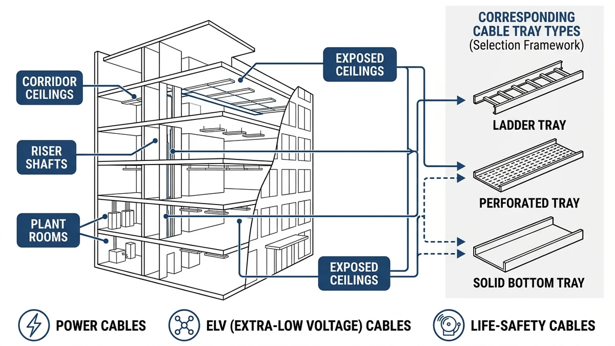
Cable tray selection for commercial buildings starts with four linked decisions: load class, environment, cable type, and maintenance strategy. In practice, you match expected working load (for example 50–150 kg/m) and span (2–3 m) to IEC 61537 or NEMA VE 1 ratings, then refine by corrosion exposure, fire strategy, and access frequency.
On office and retail projects, a practical workflow is to short-list 2–3 tray families by load/span, then eliminate options that fail corrosion (indoor dry vs. coastal parking decks), fire (escape routes vs. standard zones), or cable mix (data-heavy vs. power-heavy). This avoids overspecifying 200 kg/m cable ladders where a 75 kg/m wire tray meets both fill ratio and deflection limits, and it flags where covers or fire barriers will force tighter support spacing.
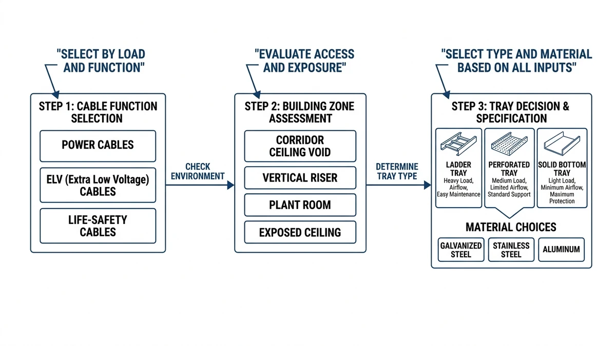
Figure 1. Core selection framework diagram showing how cable function and building zone drive tray type, material, and size choices in commercial buildings.
Choosing Tray Types by Building Zone and Cable Function
Cable tray selection for commercial buildings should start with building zone and cable function, then refine width, load class, and materials. Different areas impose different fire, access, and cleanliness constraints, which often matter more than pure kN/m strength, especially once you coordinate with ceilings, ducts, and architectural finishes.
Typical Zone–Function Combinations
Use this zone–function logic as a first pass before doing detailed calculations:
Office and retail ceilings (power + lighting, ≤400 V)
Favor: wire mesh tray or light ladder tray, 100–300 mm width.
Use when: ceiling voids see frequent layout changes, moderate loads (≤20 kg/m), and easy access.
Trade-off: very flexible for re-routing, but weaker electromagnetic shielding and less mechanical protection against impact.
Main electrical rooms and risers (feeder, submain, busduct tap cables)
Favor: heavy-duty ladder cable tray, 300–600 mm width, high load class (around 5.0–7.5 kN/m over 2.0–3.0 m spans).
Use when: large cable cross-sections, higher fault currents, and clear spacing for clamps are needed.
Trade-off: higher material cost and more coordination effort, but better fault withstand and heat dissipation.
Data rooms and BMS corridors (control, LAN, fiber)
Favor: perforated tray or wire mesh tray, 100–300 mm, with segregation dividers where needed.
Use when: many small cables, frequent churn, and EMC-sensitive circuits.
Trade-off: perforated tray supports small diameters more continuously; wire mesh is faster to cut and drop but needs careful deburring.
Car parks, plant rooms, and moist areas (pumps, HVAC, smoke control)
Favor: ladder or perforated tray with hot-dip galvanized or stainless steel, optional covers.
Use when: high humidity, IP-rated equipment, possible water spray, or chemical mist.
Trade-off: corrosion-resistant finishes and covers increase mass and may reduce allowable support spacing by roughly 10–20 %.
Escape routes and critical life-safety circuits (fire alarm, emergency power)
Favor: fire-rated cable tray systems or enclosed trunking tested as part of a circuit integrity system.
Use when: the design requires circuit integrity over 30–120 minutes.
Trade-off: limited product range and stricter support detailing; typically smaller fills but higher installation cost and inspection scrutiny.
Practical Selection Takeaway
Map each tray run to a zone and cable function, then check three items in order:
Required load class at span (kg/m).
Environment and corrosion class (indoor dry, damp, coastal, chemical).
Access and change frequency.
Only after that do you fine-tune between ladder, perforated, and wire mesh, and then confirm widths and support details.
[Expert Insight]
– In coordinated BIM models, we see 20–30 % of tray types eliminated early simply by applying zone/function rules before any structural check.
– Maintenance teams often prefer one tray family per floor; specifying by zone helps standardize while still respecting different environments.
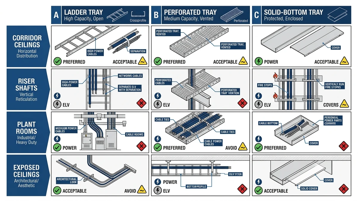
Figure 2. Tray selection matrix for commercial buildings, rating ladder, perforated, and solid trays as preferred, acceptable, or avoid across typical zones and cable functions.
Sizing, Fill, and Support Checks for Commercial Cable Trays
For a commercial cable tray to be acceptable, it must be wide enough for the required cable fill, deep enough to control stacking, and strong enough on its support spans to carry all dead and live loads with margin. These checks mirror the quick verifications many engineers run before freezing tray sizes and issuing schedules.
Step 1 – Define Cable Population and Weights
List every cable type on the route: voltage level, insulation, outer diameter (OD in mm), and grouping (power, control, ICT).
Record mass per metre from the datasheet (for example, 3.5 kg/m for a 4‑core 70 mm² PVC, 0.15 kg/m for a 2×1.5 mm² control cable).
Sum total cable weight per metre:
Example: power (40 kg/m) + control (8 kg/m) + telecom (2 kg/m) = 50 kg/m tray load.
From field measurements on mixed-use buildings, runs above 60 kg/m are common near main LV rooms, while office corridors may stay below 25 kg/m even with generous spares.
Step 2 – Check Cable Tray Width and Fill Ratio
Convert cable ODs to an equivalent occupied width. For ladder and perforated tray, a common approximation is OD × 1.1–1.2 to allow for spacing.
Select tray width so that the cable fill ratio (occupied width ÷ inside tray width) is typically:
≤40–50 % for power runs,
≤60 % for control/ICT runs,
allowing 25–40 % spare capacity for future additions.
Check that the chosen standard width (for example 300, 450, 600 mm) satisfies both initial and projected future fill.
Step 3 – Confirm Depth, Layering, and Separation
Choose tray depth (50, 75, or 100 mm are common) to avoid more than 2–3 layers of small control cables and to prevent large power cables rolling or lifting under fault forces.
If power and ELV/control share the same cable management system, ensure either:
Physical partitions or separate tiers, or
Adequate spacing in accordance with local electrical code and EMC guidance.
Step 4 – Calculate Structural Loading and Support Spacing
Add tray self‑weight (for example 5–12 kg/m for steel ladder at 600 mm width) to cable load and any allowance for future cables (often 25–50 % extra mass).
Apply a factor for installation and maintenance loads (around 1.2–1.5).
Check the resulting design load (kg/m) against the manufacturer’s load/deflection table for the chosen tray width and support span (for example 3.0 m) at the relevant temperature. IEC 61537 clause 6.2 sets out performance verification, including deflection criteria.
If the calculated load exceeds the rated load at the target deflection limit (commonly L/200), either tighten support spacing (for example from 3.0 m to 2.0 m) or move to a higher strength class.
Step 5 – Consider Special Loads and Conditions
Account for special cases:
Vertical runs: clamp spacing and pull forces during cable installation; avoid long unsupported drops.
Seismic or wind: lateral and uplift forces, potentially requiring bracing and shorter spans in certain zones.
Covers: add 2–6 kg/m for solid metal covers on wide trays, plus potential snow or debris loads outdoors.
Experience from retrofit projects shows that underestimating cover weight and extra cables can reduce real safety margin by more than 30 % if spans are not rechecked, particularly at long 3 m support distances.
[Expert Insight]
– When we overlay design loads with as-built cable counts, it is common to find 10–20 % more weight on main risers than originally scheduled, mainly from added ICT and BMS circuits.
– On projects where support spans were reduced from 3.0 m to 2.4 m in congested zones, maintenance teams reported noticeably less vibration and movement during cable pulling.
Field-Ready Shortcuts: Turning Design Rules into Installable Routes
Once the sizing logic is stable, the question becomes whether installers can build the routes cleanly with standard fittings, supports, and realistic clearances. A few disciplined shortcuts translate engineering checks into workable site layouts.
1. Choose “Standard” Heights and Widths First
To avoid custom parts and delays, lock into a small menu of tray sizes and keep exceptions rare:
Power: 100–150 mm high, 300–600 mm wide ladder tray for mains and feeders.
Control/IT: 50–100 mm high, 150–300 mm wide wire mesh or perforated tray.
If calculations suggest 420 mm width, round up to the nearest standard (typically 450 or 500 mm). This keeps tees, reducers, bends, and drop-outs off the shelf, reducing both cost and lead time.
2. Route to Fittings, Not Just to Coordinates
Instead of drawing arbitrary angles, design routes around catalog fittings:
Limit horizontal bends to 90° or 45°.
Use standard vertical risers (often 30°, 45°, 60°) for level changes.
Maintain a minimum straight length between fittings, usually 300–600 mm.
This approach reduces on-site cutting and grinding, which in turn reduces sharp edges and damage risk to cable sheaths.
3. Lock Clearances and Elevations as “Rules”
Define simple rule sets in the model and on drawings:
At least 200 mm clear above tray for cable access and heat dissipation.
Minimum 50 mm horizontal separation between power and data trays, or around 300 mm vertical offset where they cross.
Standard elevation bands, for example: power trays at +2.6 m, data trays at +2.9 m from finished floor.
When clashes occur, shift entire bands (for example up by 100 mm) instead of local “wiggles”; this keeps routes consistent and easier to support.
4. Make Supports Follow a Simple Pattern
Pick 2–3 support spans based on load class and reuse them:
Light and medium duty: 2.0–2.5 m span.
Heavy duty or heavily filled trays: 1.5–2.0 m span.
Align supports with structural modules (beams or slab grid) so trapeze frames and hanger rod lengths repeat. In our coordination reviews, this repetitive pattern has cut support detailing time by around 30 % and made later seismic checks more straightforward.
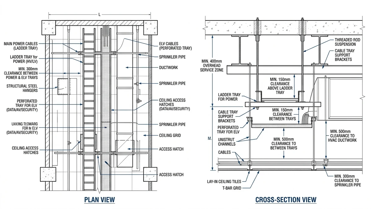
Figure 3. Corridor ceiling plan and section illustrating coordinated power and ELV cable trays, support spacing, and clearances to ductwork and sprinklers in a commercial building.
How Xinma Helps Coordinate Tray, Cover, and Support Decisions in Commercial Projects
Xinma treats the cable tray, cover, supports, and fixings as a single structural and thermal system rather than separate items on a bill of materials. That coordination becomes critical when higher cable loads (often 50–150 kg/m), outdoor corrosion class, and seismic or wind requirements interact.
Typical project decisions are tightly coupled:
Adding 1.0 mm steel covers can push a 400 mm ladder tray from a mid-range loading class to needing the next class up, or can reduce allowable support span from 3.0 m to about 2.5 m once cable and cover mass are combined.
Moving from perforated to solid-bottom tray to improve EMC or limit fire droplets often triggers ampacity derating of roughly 10–25 %, which can force an upsizing from 120 mm² to 150 mm² power cables to keep temperature rise within limits.
Switching from zinc-plated to hot-dip galvanized or stainless steel for C4/C5 corrosion environments changes both weight and bracket type, which feeds directly into seismic bracing design and anchor selection.
Xinma’s engineering support focuses on these interactions:
Checking tray loading classes to IEC 61537 and NEMA VE 1 against your calculated kg/m at the proposed spans.
Verifying that hanger rods, trapeze frames, and brackets remain within allowable stresses once covers and future cable margins are included.
Reviewing thermal derating when solid covers or higher fill ratios are introduced, referencing manufacturer ampacity data and relevant installation methods from IEC 60364.
Confirming fittings compatibility when widths or materials change, so bends, tees, and reducers maintain structural continuity and earthing/grounding paths.
In our reviews of commercial and light industrial projects, most coordination issues have been traced to one of three gaps: uncounted cover weight, unplanned future cable allowance, or underestimated corrosion and seismic demands. Addressing those early typically reduces late-stage tray rework and re-supporting by more than 50 %.
If your project is at the stage where tray routing, cover type, and support layout are being frozen, Xinma can review your tray schedules, key sections, and critical routes, then propose a coordinated tray–cover–support specification so structural, electrical, and maintenance requirements stay aligned.
For reference on performance and testing requirements, IEC 61537 can be obtained from the IEC webstore: IEC 61537 publication page.
How this page differs from related XMQJ guides
This page focuses on its stated search intent. For product-level selection, start from Xinma Cable Tray Systems and then compare the related engineering guides linked above.
Engineering Evidence and Verification Sources
This article has been updated with explicit source and procurement checks so engineering, EPC, and purchasing teams can verify the recommendations instead of relying only on generic product descriptions. For project use, treat the table below as a starting evidence map and confirm the final requirements against local codes, consultant drawings, and supplier submittals.
Use this source to verify standards, product scope, installation assumptions, or supplier evidence before final specification.
Buyer Verification Checklist
Request drawings that show tray width, depth, side rail profile, bend radius, fittings, and support spacing.
Ask for load tables or engineering assumptions that state test span, load class, and deflection criteria.
Confirm material grade, surface finish, coating method, and corrosion exposure assumptions before comparing prices.
Check whether accessories such as covers, couplers, reducers, clamps, grounding jumpers, and brackets are included.
For EPC or export orders, review packaging, labeling, inspection records, and drawing revision control before shipment.
Frequently Asked Questions
How do I choose between ladder, perforated, and wire mesh cable trays in a commercial building?
Use ladder tray for heavy feeders and long spans, perforated tray where many small or data cables need continuous support, and wire mesh for light to medium loads with frequent changes, then confirm each choice against load (kg/m), environment, and future capacity.
What fill ratio should I allow when sizing cable trays for offices and retail areas?
Aim for around 40–50 % initial fill for power trays and up to about 60 % for control and ICT trays, keeping at least one-third of the width free to accommodate cable moves and future additions without breaching thermal or access limits.
How does support span affect cable tray selection in commercial projects?
Longer support spans reduce hardware but increase tray strength requirements and deflection, so many designers cap spans at 2.0–2.5 m for heavily loaded commercial runs and only approach 3.0 m where loads and cover weights are modest and well verified.
When should I specify fire-rated cable tray systems for life-safety circuits?
Fire-rated systems are usually specified where regulations or the fire strategy require circuit integrity for alarms, emergency lighting, or smoke control over a defined duration, so they are typically applied selectively on escape routes and fire-fighting shafts rather than across all runs.
How do corrosion conditions influence the material and finish of cable trays?
As corrosion class increases from normal indoor to coastal or chemically exposed areas, materials often shift from pre-galvanized steel to hot-dip galvanized or stainless steel, which raises weight and cost but extends service life and may require stronger supports and different fixings.
Kevin Zheng
Kevin Zheng is a manager linked to Shanghai Xinma Busway & Cable Tray Co., Ltd. He writes technical content on cable tray systems, installation practice, sizing logic, load classes, and related standards for industrial and infrastructure applications.