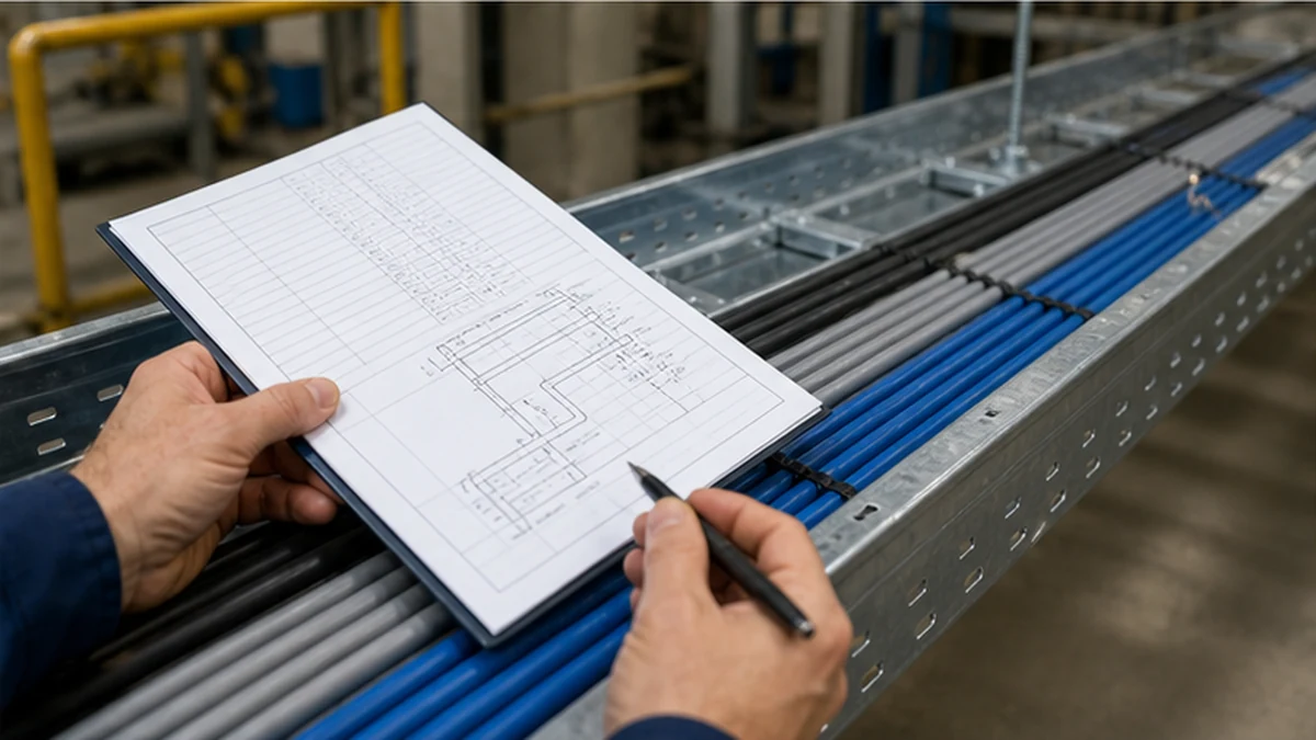
Cable tray fill ratio is a planning check, not a universal percentage that can be copied from one project to another. It compares the space required by assigned cable groups with the usable tray space, then tests whether the arrangement still satisfies the project’s installation, thermal, maintenance, and expansion requirements. A route that appears acceptably empty on a drawing can still be difficult to pull, inspect, or modify once support positions, covers, and fitting transitions are considered.
This article builds a traceable fill-ratio workflow for power, control, and data routes. If the route type is still open, first establish the relevant cable tray system and its approved widths, depths, fittings, and support arrangement before beginning any occupancy calculation.
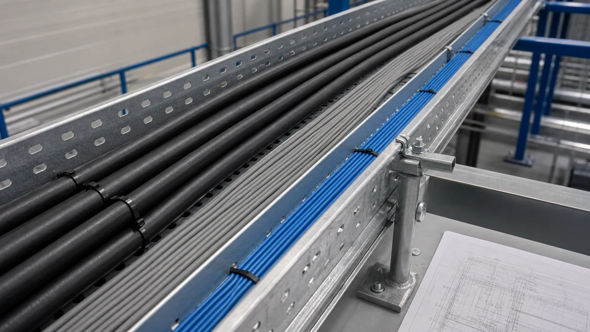
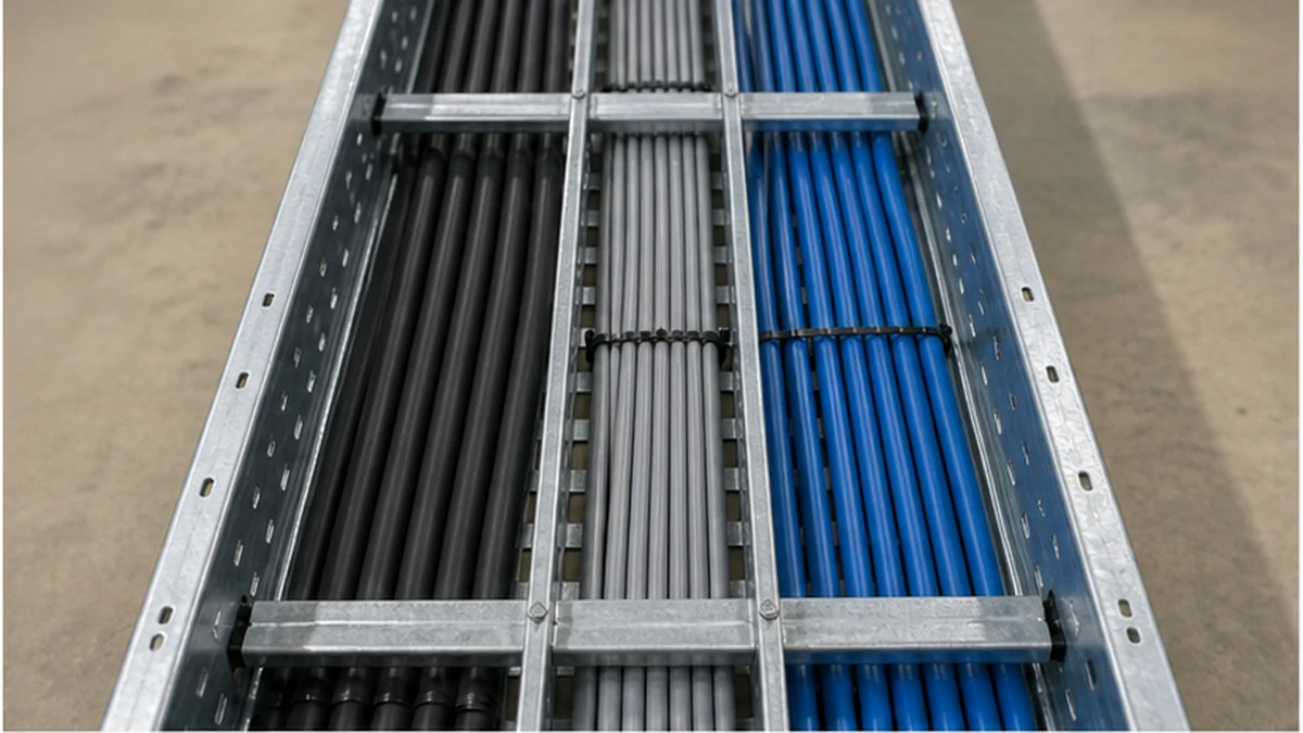
Cable tray cable lanes
Define the Calculation Boundary Before Counting Cables
The calculation begins with the approved route, not with a tray catalog table. Identify the cable family assigned to each run, the usable length and width of each tray section, any divider lanes, covers, fittings, changes in elevation, and the points at which cables enter panels or equipment. Record whether the route carries single conductors, multi-core power cables, control cable, fiber, communications cable, or a mixture, because each group may have different arrangement rules.
The usable tray area is not the same as the nominal product width multiplied by the nominal sidewall height. Side rail geometry, divider position, internal obstructions, hold-downs, splice hardware, bend sections, and access requirements can all reduce the practical routing space. For multi-layer arrangements, the cable designer should state the permitted stacking method and whether restrictions apply to cable grouping, separation, or heat dissipation.
IEC 61537 addresses cable tray and ladder systems as products. Consult the IEC 61537 publication alongside the project’s electrical design documents. Do not use a tray-product reference as a substitute for the governing cable installation or ampacity design.
Collect and Record Source Data
Use the latest approved cable schedule and manufacturer data sheets. For every cable group, capture the following inputs before calculating occupied area.
Input field
Source document
Notes
Cable outside diameter
Manufacturer data sheet
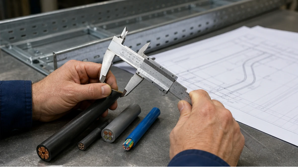
Use actual OD, not nominal conductor size
Cable quantity per route
Approved cable schedule
Record schedule revision and date
Service type
Cable schedule
Power, control, data, or fiber
Route length
Issued route drawing
Note revision used
Installation phase
Project programme
Identify cables not yet issued
Tray nominal width and depth
Tray product data sheet
Confirm usable versus nominal dimensions
Divider position and width
Tray product data sheet
Affects lane width for each group
Future-capacity reservation
Client brief or design basis
State assumption explicitly
For round cables, occupied cross-sectional area is commonly derived from the actual outside diameter. For irregular bundles, flat cables, or grouped assemblies, use the geometry stated by the manufacturer or a documented project method. The calculation should show every input and the rounding rule applied, so a later change in cable size can be assessed without rebuilding the full route model.
Separate cable groups when the design calls for separate lanes. A power feeder, a control group, and a communications bundle must not be combined into one undifferentiated total merely because they share a tray corridor. The required arrangement affects lane width, divider selection, pulling sequence, and cover choice. If the final cable selection has not been issued, label the calculation as preliminary and state the assumed diameter rather than presenting it as confirmed.
Cable tray fill calculation inputs
Nominal Dimensions Versus Usable Space
Understanding the difference between a tray’s labeled size and its actual routing capacity is essential before any fill ratio is calculated. The table below describes the common deductions that apply to a standard tray section.
Dimension type
What it represents
Typical deduction source
Nominal width
Catalog label, e.g., 300 mm or 450 mm
Starting reference only
Usable width per lane
Nominal width minus side rail thickness and divider width
Side rail geometry, divider plate thickness
Usable depth
Nominal sidewall height minus cable-cleat or hold-down projection
Cleat height, cover-clamp intrusion
Fitting transition space
Reduced at elbows, tees, and reducers
Fitting geometry, bend radius
Access allowance
Space reserved for pulling tools and maintenance
Project or installation standard
These deductions vary by tray product and project requirement. The calculation must use the confirmed usable dimension for each lane, not the nominal catalog value, and must cite the product drawing or data sheet from which the usable figure was taken.
Account for Installation and Thermal Conditions
Physical occupancy is only one check. Crowded routes can make cable pulling harder, block access to cleats or supports, complicate maintenance, and alter the conditions assumed in the cable rating. Covers, sunlight exposure, ambient heat sources, cable grouping, and long parallel runs should each be reviewed by the electrical designer where they apply to the route.
Avoid concluding that a tray is acceptable solely because it meets one percentage threshold. The permissible utilisation must come from the project’s electrical and installation requirements, the cable manufacturer’s information, and the approved design method. If the calculation is used to release a purchase order, preserve the source revision of every cable schedule and drawing used as part of the calculation record.
Where a control-cable package changes its outside diameters between design stages, the revised geometry should be re-entered into the route model before pulling begins. Moving affected cables to a planned adjacent lane before supports and dividers are installed avoids field decisions that can compromise the intended separation or thermal arrangement.
Compartment-by-Compartment Review
When a route uses compartments or divider lanes, calculate each compartment separately. Do not allocate unused area in one lane to a cable group that the design requires to remain segregated. Confirm that dividers, cover clamps, splice plates, and fitting transitions preserve the same lane arrangement throughout the full route length.
A compartment-by-compartment review follows this sequence:
List every compartment by label, assigned service, and lane width.
Calculate occupied area for the cables assigned to that compartment.
Compare occupied area with confirmed usable area for that lane.
Record the result and the drawing revision used.
Repeat for the next compartment before combining results into a route summary.
This sequence prevents a well-utilised lane from being masked by a lightly loaded adjacent lane in a combined total. It also produces a compartment-level record that can be updated independently when one cable group changes without affecting the others.
For perforated cable tray systems, verify available width, depth, divider fixing method, and support pattern in the selected product before assigning lane widths. Where the route is a heavily supported power run, ladder tray or another system may be more appropriate; that decision should be based on the approved cable and mechanical design.
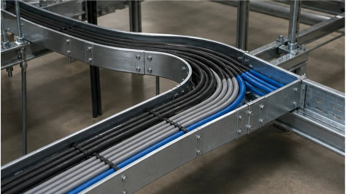
Fill check at tray fittings
Check Fittings, Entries, and Future-Capacity Records
Straight-length calculations can conceal the real constraint. Review elbows, tees, crosses, reducers, risers, expansion locations, wall entries, and equipment drop-outs. These locations can change available bend space, force a cable group to cross lanes, or require a larger fitting than the straight run suggests.
The bill of materials should identify tray sections, matching fittings, divider pieces where used, covers, fasteners, and support components. Use the cable tray fittings range to cross-check system compatibility, then obtain a route-level takeoff. A generic fitting length should not be used to infer usable cable capacity at a transition.
Future capacity must be explicit in the calculation record. If the client expects additional feeders, controls, or data circuits, reserve the planned lane or tray space on the drawing and note the assumptions that apply. Do not classify all open space as spare when it is already needed for pulling access, lane separation, or a cable package not yet issued. A future-capacity record should state the service type, estimated quantity, assumed outside diameter, and the lane or tray section reserved.
Pre-Pull Verification Checklist
Before cable pulling begins, compare the installed tray and fittings with the approved calculation. The following checklist supports that hold point.
Check item
Verified by
Pass condition
Tray width and depth match calculation inputs
Site engineer
Confirmed usable dimensions recorded
Divider position matches lane layout drawing
Site engineer
Lane widths consistent with calculation
Fittings match system and route drawing
Procurement or site
Compatible product codes confirmed
Support positions match approved layout
Site engineer
No unplanned obstructions to cable access
Cover type and fixing match design
Site engineer
Cover clearance confirmed at entries
Cable outside diameters match data sheets
Cable installer
Actual OD checked against calculation input
Pulling sequence matches lane allocation
Cable installer
Later groups do not require removal of earlier ones
Future-capacity reservation marked on drawing
Designer
Reserved lanes clearly identified
Mark the assigned cable lanes on the coordination drawing and arrange the pulling sequence so crews do not have to remove completed bundles to install later groups. The cable tray installation guide provides broader execution context. Add a hold point at the first representative installation to confirm actual cable diameters, lane allocation, bend access, and cover clearance before the full route is populated.
Support conditions belong in the same review because they determine where the route can be accessed and how the cable assembly behaves between fittings. Check the approved support layout, hanger positions, and clearance to tray hardware against the final cable grouping. The cable tray support planning guide provides broader context for that coordination. Where a divider, cover clamp, cleat, or splice occupies part of the available working space, the fill calculation should cite the drawing revision used so a later support change does not silently invalidate the route assumptions.
If a field connector or cable assembly proves larger than the listed dimension at the hold point, record the variance and revise the entry detail before continuing. Treating the straight-run calculation as proof that every transition will fit is a common source of late-stage field changes.
Xinma System Coordination
Xinma manufactures cable tray sections together with a coordinated range of fittings, lane dividers, cover systems, busway, and seismic-bracing components. In a fill-ratio review, the practical benefit of a single-source system is the ability to compare model codes, confirmed tray geometry, support spacing, divider interface dimensions, and fitting availability on one coordinated bill of materials. That alignment gives procurement teams a clearer record of what was calculated and gives site inspection teams a direct reference for verifying that the installed configuration matches the approved route model. Where seismic-bracing requirements apply, Xinma bracing components are designed for compatibility with the same tray sections and support hardware used in the fill calculation, reducing the risk of geometry conflicts at brace attachment points. Before finalising the BOM, cross-check divider fixing methods, cover-clamp profiles, and fitting transition lengths against the usable-space figures used in the compartment calculations to confirm that no hardware addition reduces a lane below its calculated available area.
Cable tray fill hold point
Frequently Asked Questions
Is there one standard cable tray fill ratio for every project?
No. The allowed use of tray space depends on the governing project requirements, cable data, installation method, thermal conditions, and route layout. A single percentage applied across all routes and cable types is not a substitute for a route-specific calculation using confirmed inputs.
Should power, control, and data cables be counted as one total?
Only if the approved design permits the same lane and arrangement for all groups. Where separation is required by the design or installation standard, calculate and document each assigned compartment separately and confirm that the lane arrangement is maintained through fittings and entries.
Does nominal tray width equal usable cable space?
Not necessarily. Side rails, dividers, fittings, hardware projections, access requirements, and cable arrangement rules can all reduce the practical routing space below the nominal catalog dimension. The calculation must use confirmed usable dimensions for each lane, referenced to the product data sheet or drawing.
When should a fill calculation be updated?
Update it when cable quantity, outside diameter, route geometry, tray system selection, divider layout, cover condition, support arrangement, or future-capacity assumption changes. Each update should record the drawing and schedule revisions used so the calculation history remains traceable.
Why are fittings important in a fill-ratio review?
Elbows, tees, reducers, risers, and equipment entries may create the real space or bend constraint on a route even when straight tray sections appear adequate. Fitting geometry, transition length, and bend radius can reduce available cable space and affect the pulling sequence in ways that a straight-run calculation does not capture.
Kevin Zheng
Kevin Zheng is a manager linked to Shanghai Xinma Busway & Cable Tray Co., Ltd. He writes technical content on cable tray systems, installation practice, sizing logic, load classes, and related standards for industrial and infrastructure applications.