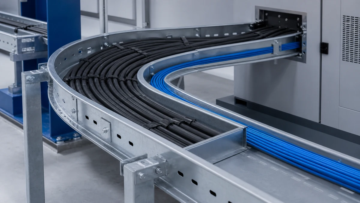
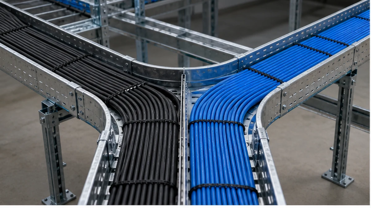
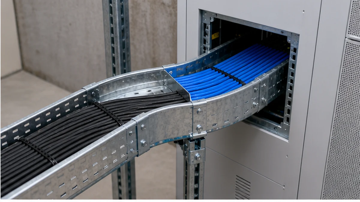
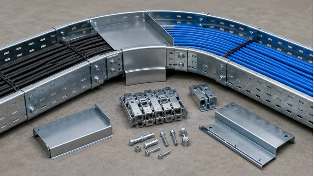
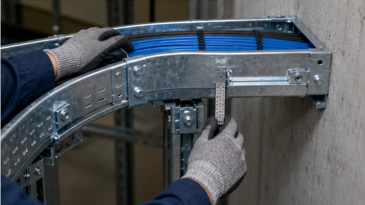
Cable tray bends guide a cable route around a change in direction. They do not, by themselves, establish the minimum bend radius for every cable assigned to that route. Power, control, fiber, and hybrid cables can carry different manufacturer limits for installation and for final service. The tray fitting, cable arrangement, pulling method, and equipment-entry geometry must all allow those limits to be met without forcing a cable against a sharp edge or across another cable group. Understanding where tray-fitting geometry ends and cable-specific requirements begin is the practical starting point for route planning.
Begin by confirming the cable tray system and the cable families assigned to it before selecting any fitting or planning a pulling sequence.
Cable tray bend cable lanes
The Difference Between Cable Bend Requirements and Tray-Fitting Geometry
These are two distinct engineering inputs that are sometimes treated as a single value. They are not.
Cable manufacturer bend requirements are a property of the cable construction. The cable supplier’s data sheet states a minimum inside radius—often given separately for the installation condition and the final service condition—that must not be violated at any point along the route. This value accounts for the conductor, insulation, screen, armour, jacket, and in the case of fiber, the optical-waveguide geometry. Exceeding it risks immediate damage to screens or optical fibres, or cumulative degradation that is not visible at commissioning.
Tray-fitting geometry describes the inside radius of the elbow, offset, or transition piece itself. A 45-degree or 90-degree elbow with a stated inside radius tells you where the side rail curves. It does not account for how cables of different diameters sit within the fitting, how they stack or splay, or what happens at the point where the cable leaves the fitting and approaches a gland, drop-out, or panel opening.
The practical consequence is straightforward: a tray elbow whose inside radius appears adequate may still create a violation at the cable nearest the inner rail, or at the first support point beyond the fitting. Both inputs must be reviewed together, route node by route node.
Key distinctions at a glance
Input
Source
What it governs
Cable minimum bend radius (installation)
Cable manufacturer data sheet
The smallest permissible radius the cable may make during pulling
Cable minimum bend radius (service)
Cable manufacturer data sheet
The smallest permissible radius in the final installed position
Tray fitting inside radius
Fitting supplier catalog or drawing
The geometry of the tray component itself
Effective cable radius at inner rail
Calculated from fitting radius + cable position in tray
The actual bend condition for cables closest to the inner rail
Effective cable radius at outer rail
Calculated from fitting radius + tray width + cable position
The condition for cables sitting at the outer side
Where national or project standards apply to the tray system as a product, IEC 61537 provides relevant classification and test context. It does not replace the cable-specific data that controls the installed route.
Use Cable Manufacturer Data as the Primary Design Input
Obtain the current data sheet for each cable family before selecting the fitting or finalising the route. Record the outside diameter, the minimum bend condition for installation and service where both are provided, pulling restrictions, permitted support method, and any limit on sidewall pressure or tension. Do not apply a single bend rule across power conductors, control cables, and fiber; their construction and sensitivity to bending differ in ways that matter at congested or tight turns.
The route drawing should identify cable groups and flag the location of every elbow, tee, reducer, riser, drop-out, panel entry, and transition to conduit or equipment. The design team can then confirm whether the selected fitting geometry and available free space allow the governing cable to complete each turn without unwanted compression, crossing into an adjacent lane, or contacting a structural edge.
Route-Node Worksheet
Treating the route as a series of nodes—rather than as a continuous run interrupted by occasional bends—helps identify where conflicts are most likely before pulling begins.
Recommended node types and checks
Node type
Primary check
Secondary check
Horizontal elbow
Effective cable radius at inner and outer rail versus governing cable data sheet
Lane continuity through fitting; divider transition present if required
Vertical riser
Cable splay and weight distribution on inner rail; support within manufacturer interval
Armour or jacket contact with rung or edge at entry to riser
Equipment entry / gland plate
Minimum radius at the gland approach, not just inside the tray
Twist or crossing between cable groups at the final approach
Drop-out
Radius at the point of departure from the tray floor or side
Support location relative to the drop; unsupported length within permitted range
Reducer / transition
Width change and cable lane alignment through the narrowing
Cover or divider detail that accommodates the width step
Conduit transition
Bending radius at the conduit entry bell mouth or fitting
Pulling tension limit if cable continues into conduit beyond the transition
Support / hanger
Does hanger position restrict cable movement during pulling at an adjacent bend?
Does it create an unsupported cantilever at a fitting?
Pulling sequence node
Is the planned pull order achievable given cable-lane assignments?
Is temporary roller or guide placement identified?
Complete this worksheet for each node on the approved route drawing before ordering fittings or releasing cable procurement. Update it if the route changes during installation.
Select the Tray Fitting as a System Component
A tray elbow must match the selected tray’s width, side rail profile, material, finish, splice arrangement, support method, and any divider or cover detail. A bend that is mechanically compatible with the straight tray may still be unsuitable if it does not provide an orderly path for the largest or most geometrically sensitive cable group.
On ladder cable tray, check the rung spacing within or adjacent to the fitting, the side-rail contact edge, cable-support points through the turn, and any required cable-retention hardware. For shared routes, preserve the approved lane arrangement through the fitting. Do not allow a fiber bundle to cross a power cable group at the elbow simply because the straight sections are separated.
Use the cable tray fittings range to confirm that the selected elbow and any transition hardware belong to the same system family. Catalog compatibility alone does not confirm that the governing cable can complete the route. Cross-reference the fitting drawing against the cable schedule and the route-node worksheet before finalising the bill of materials.
Cable tray bend entry detail
Plan Equipment Entries, Drop-Outs, and Pulling Sequence
The governing bend condition on a route is often not the open tray elbow. It is frequently a panel gland plate, a drop-out, a wall-sleeve opening, a conduit transition fitting, or the first support point after an elbow. Review the complete approach to each piece of equipment and confirm that every cable can be pulled and positioned without sharp contact, excessive twist, or disturbance to previously completed cable groups.
Pulling sequence affects whether these conditions can be met.
Pulling sequence considerations
Pulling the largest power cable first provides a physical reference for available space, but may leave the cable exposed if lighter cable groups must be pulled over it later.
Pulling a sensitive fiber bundle first protects it from contact during subsequent heavier pulls only if the routing and lane assignment keep subsequent cables away from the bundle.
Where routes share a vertical drop with a horizontal run, establish whether the cable must be fed from above or below before positioning temporary rollers or bending guides.
Identify pull points, tension limits, and guide placement on the route drawing rather than resolving them at the time of pulling.
If a cable must pass through a conduit section connected to the tray, co-ordinate the tension calculation for both sections before pulling begins.
Coordinate Fittings, Dividers, Covers, and Supports
The bill of materials should include the matching elbow or radius fitting, splice pieces, divider transitions, cover pieces where used, cable-retention hardware, and support components. A divider that terminates before a fitting does not preserve the documented cable arrangement through the turn. A cover that cannot follow the fitting profile may also change the maintenance access or environmental exposure condition that the design assumed.
Supports must be positioned so they do not obstruct cable movement at the turn or create an unsupported section at an equipment entry. Confirm hanger, bracket, and cleat positions against the route-node worksheet before installation. The cable tray support planning guide provides coordination detail for hanger intervals, load points, and seismic-restraint locations relative to fittings.
Cable tray bend system fitting
Pre-Pull Inspection Checklist
Install one representative route detail—including at least one elbow, one equipment entry, and one drop-out—before releasing cable pulling across the whole route. Inspect that assembly against the approved drawing and record any change before the condition is repeated elsewhere.
Pre-pull inspection checklist
[ ] Fitting inside radius confirmed against route-node worksheet for governing cable
[ ] Cable lanes marked or physically separated through fitting (dividers, spacers, or documented lane discipline)
[ ] Divider and cover transitions installed and aligned; no abrupt termination at fitting entry or exit
[ ] All edge conditions checked for burrs, weld spatter, or finish discontinuity that could contact cable jacket
[ ] Support positions confirmed; no hanger blocks cable movement at adjacent fitting
[ ] Drop-out geometry and support location reviewed; unsupported length within permitted range
[ ] Equipment-entry approach checked for radius at gland plate or sleeve; cable approach angle assessed
[ ] Temporary rollers, pulling guides, and bend-protection sleeves positioned at planned pull points
[ ] Pulling sequence confirmed against cable-lane assignment and equipment-entry order
[ ] Completed assembly compared to approved drawing; any discrepancy recorded before proceeding
[ ] Responsible person has signed off on representative section before general pulling begins
Cable tray bend inspection
Xinma System Coordination
Xinma manufactures cable tray sections together with fittings, accessories, busway distribution components, and seismic-bracing hardware. At a cable bend, the practical coordination check is whether fitting geometry, divider and cover transitions, support interfaces, seismic-restraint attachment points, and material finish are drawn from a matched system and appear together on a single bill of materials. Mixing components from mismatched system families can create splice gaps, divider misalignment, or support incompatibilities that are difficult to identify from a drawing alone. Xinma’s site-inspection support can assist in comparing delivered components to the approved route detail node by node, confirming that busway connections near tray transitions do not introduce bend constraints that the tray design did not account for, and verifying that seismic-bracing attachments do not conflict with fitting or support positions identified in the route-node worksheet. This coordination is most effective when it begins at the BOM stage rather than at the point of installation.
Frequently Asked Questions
Is a cable tray elbow radius the same as a cable minimum bend radius?
No. The cable requirement is a property of the cable construction and is stated by the cable manufacturer. The tray fitting radius describes the geometry of the tray component. A fitting whose inside radius appears sufficient may still create a bend violation for cables sitting near the inner rail, or at the point where the cable transitions from the fitting to an equipment entry. Both inputs must be reviewed and reconciled for each cable group on the route.
Which cable should govern the bend check on a shared tray route?
Check every assigned cable family and design the fitting geometry and lane arrangement around the most restrictive condition. Cables with different outside diameters, constructions, and pulling sensitivities do not share a single governing value. Assuming they do risks a violation that is not visible until the cable is in service or undergoing testing.
Are straight tray sections and open elbows sufficient to verify cable bending compliance?
No. The critical bend condition is often at a panel gland plate, a drop-out, a wall sleeve, a conduit transition, or the first support point beyond a fitting. Each of these locations should be treated as a route node and checked individually against the relevant cable data sheet before pulling begins.
Can a divider terminate at a tray elbow without a transition piece?
Only if the approved route design explicitly documents how the cable groups remain separated through and beyond the fitting. Without a compatible transition detail, the lane separation established on the straight run is lost at the turn, and cables may cross between groups in a way the design did not intend. Provide a coordinated transition detail wherever lane discipline must be maintained through a fitting.
Why install and inspect a representative bend assembly before general cable pulling?
Because the approved drawing cannot verify actual fit, edge condition, support position, cover alignment, and pulling access simultaneously. A representative assembly reveals route-interface issues—such as a support location that blocks cable movement at a drop-out—while changes are still practical and before those conditions are repeated across multiple route sections.
Kevin Zheng
Kevin Zheng is a manager linked to Shanghai Xinma Busway & Cable Tray Co., Ltd. He writes technical content on cable tray systems, installation practice, sizing logic, load classes, and related standards for industrial and infrastructure applications.