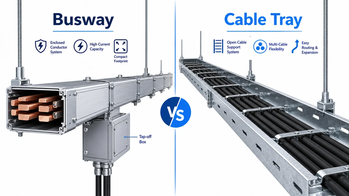
Busway and cable tray solve different parts of an electrical distribution route. A busway is a prefabricated conductor system for carrying current through enclosed busbars. A cable tray is a support pathway that carries insulated power, control, or data cables. In project selection, the question is not which product is “better”; it is whether the route needs a current-carrying system or an organized cable-support system.
For high-current feeders, vertical risers, repeated tap-off points, and clean expansion, busway systems often simplify routing. For mixed cable schedules, control wiring, low-voltage routes, communication cables, and field-adjusted layouts, cable tray systems usually fit better. Many industrial buildings, data centers, and commercial projects use both.
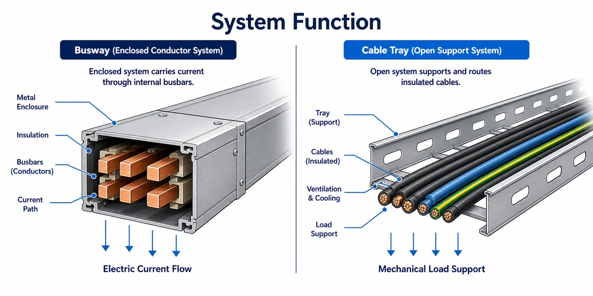
Busway is the current-carrying system; cable tray is the support pathway for insulated cables.
The Core Difference: Conductors vs Cable Support
Busway, also called bus duct or busbar trunking, contains copper or aluminum busbars inside a metal enclosure. The enclosure is not just a support shell; it is part of a tested electrical system that includes conductor spacing, insulation, joints, tap-off interfaces, short-circuit withstand, temperature rise, and enclosure protection.
Cable tray does not carry power by itself. It supports cables that already contain their own conductors, insulation, jackets, shielding, and fire-performance properties. A ladder, perforated, or solid-bottom tray route is selected around cable fill, bend radius, load per meter, support span, segregation, corrosion environment, and access for maintenance.
This distinction changes the engineering workflow. When specifying busway, the design starts from load current, voltage, fault level, number of taps, route length, installation orientation, and certification evidence. When specifying tray, the design starts from the cable schedule, cable outside diameters, fill reserve, weight, route changes, support arrangement, and environmental finish.
When Busway Fits Better
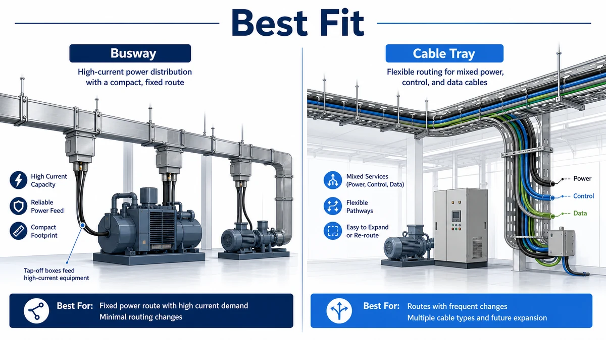
Busway fits best when a project needs compact high-current power distribution with predictable geometry. Typical examples include transformer-to-main-switchboard feeders, production-line tap-off distribution, high-rise risers, data hall power corridors, and commercial building vertical distribution.
The strongest busway advantage is current density. A 1600 A or 2500 A route can often be made cleaner with enclosed busbar trunking than with multiple parallel cable sets, especially when floor or ceiling space is limited. Busway also reduces the number of separate cable pulling operations. Standardized sections, elbows, offsets, joint packs, and tap-off boxes make the route modular if the drawings are stable.
In an anonymized 2024 commercial retrofit in Shanghai, the electrical team compared a 48 m vertical feeder route using parallel low-voltage cables against a 2000 A aluminum busway. The busway option reduced riser-space occupation by roughly one third and simplified later tenant tap-off planning. Those figures are project-specific, but they show the real selection logic: busway becomes attractive when space, branch expansion, and installation sequencing matter.
Busway is not automatically easier. The supplier must verify joint design, conductor material, enclosure rating, temperature-rise test evidence, tap-off compatibility, and short-circuit withstand. IEC 61439-6 is the relevant international standard for busbar trunking systems, and the official publication page is available from the IEC webstore.
When Cable Tray Fits Better
Cable tray fits better when the project contains many cable types, route changes, or field-adjusted branches. A cable tray can carry power cables, control cables, instrumentation cables, fiber, network cables, and auxiliary wiring, provided segregation and project rules are followed. It is more adaptable when the route is likely to change during construction.
A tray route is also easier to inspect visually. Installers can see cable grouping, tie-down points, bend radius, spare capacity, and whether cables have been stacked poorly. For heavy power cables, ladder cable tray gives airflow and support. For mixed or lighter routes, perforated tray may provide a better balance of support, drainage, and inspection.
Cable tray is usually the right starting point when the load is not a single high-current feeder. It is also a better fit for long routing areas where different cable systems share the same corridor but need separation. In these cases, choosing busway would force the project into a conductor-system solution when the real task is cable organization.
The practical risk with tray is underestimating support and fill. If the route is treated as a simple metal channel, the system can sag, overload supports, damage cable jackets, or block later maintenance access. A proper tray selection should reference cable weight, side height, tray width, support span, fittings, covers, bonding, and future reserve.
Route Stability and Field Flexibility
Busway rewards stable design. Once the route, bends, tap-off positions, and vertical offsets are fixed, prefabricated sections can be made accurately and installed quickly. But late site changes are expensive. A shifted wall opening, changed equipment position, or revised tap-off height can affect multiple sections.
Cable tray tolerates field changes better. Installers can adjust fittings, shorten sections, change supports, and re-route cables with less impact on the core electrical product. This is useful in industrial plants where equipment foundations, pipe racks, HVAC ducts, and process skids may move during coordination.
For EPC teams, this means busway should be locked after a stronger drawing review. Cable tray can be released earlier if the project team has clear support rules and enough route reserve. A mixed strategy is common: busway for stable high-current backbone routes, tray for branch wiring and control systems.
Installation Checks Are Different
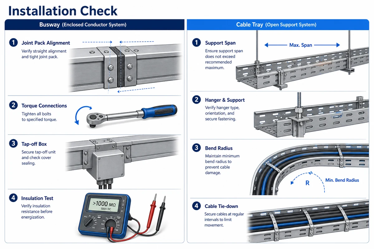
Busway installation quality is decided at the joints. A good site checklist includes section alignment, joint-pack cleanliness, torque sequence, insulation resistance test, enclosure continuity, tap-off box orientation, hanger spacing, and expansion allowance. The installer should also confirm that all sections match the route drawing and that phase sequence is consistent.
Cable tray installation quality is decided by support layout, fittings, cable protection, and route access. The tray should not be overloaded at fittings. Supports should be placed close to bends, tees, risers, and heavy cable entry zones. For buyer-side review, the existing XMQJ guide on cable tray support is a useful reference because support spacing often becomes the hidden failure point.
Busway installation focuses on joints and tap-offs; tray installation focuses on support span and cable protection.
An anonymized 2023 industrial plant review in Suzhou found that a proposed cable tray route was suitable for control and auxiliary power cables, but not for a main feeder that required repeated machine tap-offs. The revised plan kept cable tray for control circuits and used plug-in busway for the production-line power backbone. The change reduced cable-pulling complexity and made future machine relocation easier, while keeping tray flexibility where it mattered.
Cost Logic: Material Price Is Not the Whole Decision
Busway often looks more expensive when compared only by meter price. That comparison is incomplete. A busway quote includes conductors, enclosure, joints, tap-off interfaces, testing, and prefabricated route logic. A cable route may require cables, tray, supports, fittings, pulling labor, termination labor, larger bend space, and more coordination time.
Cable tray often wins when current is moderate, cable types are mixed, or the route needs frequent field adjustment. Busway can win when current is high, space is tight, installation time is constrained, or future tap-offs have commercial value. The right comparison is total installed route cost, not catalogue price.
Procurement teams should request a bill of materials from both options. For busway, check section length, conductor material, current rating, IP rating, tap-off count, joint kits, hangers, and test documentation. For tray, check tray type, material finish, thickness, support spacing, fittings, covers, grounding accessories, and cable schedule assumptions.
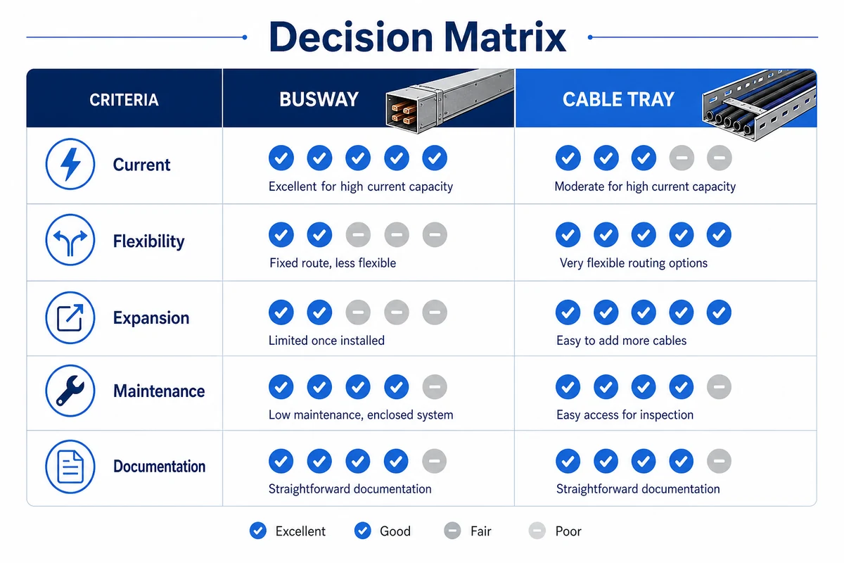
Decision Matrix for EPC and MEP Teams
Use busway when the route is a high-current power backbone, the layout is stable, space is limited, tap-offs are repeated, and the supplier can provide standard-compliant test evidence. Use cable tray when the project needs flexible cable routing, mixed cable systems, visible inspection, lower-current branches, or future cable additions.
The best choice depends on current, flexibility, expansion, maintenance access, and documentation.
A simple decision sequence works well:
Start with the load schedule. If the route is one high-current feeder or a repeated power backbone, evaluate busway.
Check cable diversity. If the route carries many different cable types, evaluate tray first.
Check design stability. If equipment positions are not fixed, tray is usually more forgiving.
Check space. If riser or ceiling space is constrained, busway may reduce route volume.
Check maintenance. If visual cable inspection and future pull-in matter, tray has an advantage.
Check documentation. If the option lacks test reports, drawings, and installation rules, do not select it only on price.
The best projects do not force one system everywhere. They divide the building into power backbone zones, branch distribution zones, control wiring zones, and maintenance-access zones.
Supplier Information to Request Before Quotation
For busway, send the single-line diagram, rated current, voltage, fault level, route length, number of elbows, vertical or horizontal orientation, tap-off positions, IP rating, conductor preference, and installation environment. Ask for type-test evidence, joint details, temperature-rise data, and installation manual.
For cable tray, send the cable schedule, cable diameters, cable weights, desired reserve, route drawings, support conditions, material preference, corrosion exposure, firestopping requirements, and cover needs. The article on product-family review guide is a good starting point before a detailed takeoff.
Shanghai Xinma manufactures busway, cable tray, fittings, accessories, and seismic bracing components within the same product ecosystem. That matters when a busway backbone and tray branch routes share the same ceiling zone, when brackets and hanger locations must be coordinated, and when a project needs repeated deliveries across several phases. The value is not a marketing ranking; it is the ability to keep model codes, finishes, support geometry, and inspection documents consistent from bill of materials to site inspection.
When specifying Xinma products, use the live busway product page as the primary landing page for enclosed power routes, and cross-check cable routing compatibility against the relevant cable tray system and seismic bracing pages before finalizing the order.
Frequently Asked Questions
Is busway the same as cable tray?
No. Busway is an enclosed conductor system that carries current through busbars. Cable tray is a support pathway for insulated cables. They may appear in the same electrical route, but they are specified, tested, installed, and inspected differently.
When should I choose busway instead of cable tray?
Choose busway when the route is high-current, space-limited, stable in geometry, and likely to need repeated tap-off points. It is common for transformer feeders, risers, production lines, data centers, and large commercial buildings.
When is cable tray better than busway?
Cable tray is better when the route carries mixed cable types, needs field flexibility, requires visual inspection, or may change during construction. It is also the normal choice for control, data, instrumentation, and many branch power cables.
Can busway and cable tray be used together?
Yes. Many projects use busway for the main power backbone and cable tray for branch cables, control wiring, communication cables, and auxiliary systems. The key is to separate current-carrying distribution from cable-support routing.
What information should I send for a comparison quote?
Send the load schedule, single-line diagram, route drawing, cable schedule, installation environment, space limits, tap-off needs, support conditions, and required standards. Without those details, suppliers can only make rough assumptions.
Kevin Zheng
Kevin Zheng is a manager linked to Shanghai Xinma Busway & Cable Tray Co., Ltd. He writes technical content on cable tray systems, installation practice, sizing logic, load classes, and related standards for industrial and infrastructure applications.