Professional Bridge &
Bus Tray Solutions

Get premium quality cable management systems directly from the manufacturer.

  • ISO 9001 Certified Quality
  • Factory Direct Pricing
  • Fast Global Delivery

Request A Quote

Fill out the form below to receive our catalog and pricing.

Contact Form Demo
Busway Systems

Busway Systems for
Modular Power Distribution

Build scalable bus duct (busbar trunking) routes for industrial and commercial power distribution. Choose conductor material (copper / aluminum), select feeder or plug-in layout, then complete the run with joints, fittings, tap-off boxes, and support hardware—matched to your drawings and site conditions.

CU Copper Conductor Option
AL Aluminum Conductor Option
RUN Feeder + Plug-in Layout
● Layout & BOM support ● Indoor / Outdoor-ready options ● Project-based configuration

System Snapshot

PROJECT READY

Start with your SLD and route plan, then confirm current rating, conductor choice, and plug-in needs. We’ll align section list, joint logic, and tap-off schedule to your installation method.

Conductor Options

Copper or aluminum conductors for different loss, weight, and cost priorities.

Feeder / Plug-in

Fixed feeder runs or plug-in sections for flexible, scalable power distribution.

Joint Pack

Connection logic designed for consistent assembly and inspection on site.

Fittings & Supports

Elbows, tees, offsets, risers, hangers, and accessories to complete the route.

Selection Guide

How to Specify Busway
for Real-World Power Distribution Routes

System Topology

COMPONENT MAP
Busway system diagram

Key Components

  1. Trunking Unit (Straight)
  2. Tap-off Unit (Plug-in)
  3. Joint Pack (Connector)
  4. Feeder Unit (Source)
  5. Flange End (Switchboard)
  6. Elbow/Offset (Fittings)
  7. Hangers (Mounting)
  8. End Cap (Termination)
Busway (bus duct) is a prefabricated power route. A correct takeoff starts from the electrical intent (current & system) and the physical route, then confirms conductor choice and protection level.
Input Current (A)
Input Layout Drawing
Select Conductor
Select IP Rating
1

Material Choice

Decide between Copper (performance) or Aluminum (cost/weight) based on project budget and loss requirements.
Copper Aluminum
2

Feeder vs Plug-in

Use “Feeder” for main transmission runs, and “Plug-in” sections where you need tap-off boxes for distribution.
Feeder Plug-in
3

Route Engineering

Convert the physical path into a BOM: straight lengths, elbows (L), tees (T), and offsets (Z) to fit the building.
Layout Fittings
4

Project Output

Generate the final Section Schedule and Joint Kit list so installation is predictable and error-free.
BOM Install
Product Datasheet

XMMX-XL System Specifications

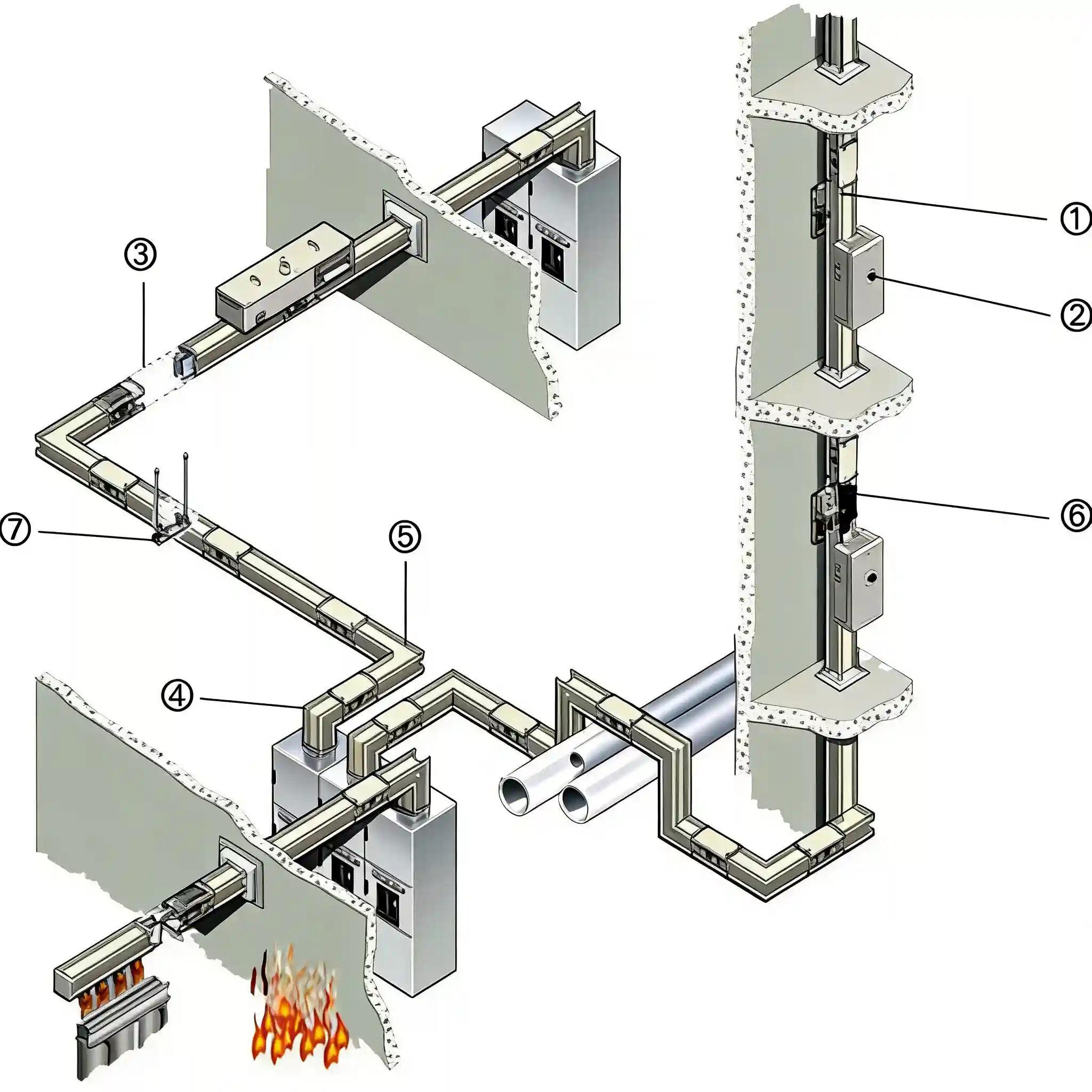
Technical engineering data derived from the product catalogue. Refer to the System Map below for component identification.

Complete XMMX-XL Busway System Component Map referencing items 1 through 7
Figure 1: System Component Map — Showing ①Trunking ②Tap-off ③Joints ④Feeders ⑥Fittings

Straight Trunking Units

Core transmission units featuring dense “Sandwich” insulation and aluminum alloy enclosure (PE > 100%). Available in Copper (C-Series) and Aluminum (A-Series) conductors.
Item Ref: ① Standard Length: 4m / 3m IP Rating: IP54 / IP65
Table 1.1: XMMX-XL C (Copper) Parameters Ref: Page 11
Current (A) Icw (kA) Resistance (mΩ/m) Impedance (mΩ/m) Dimensions (mm)
400300.1090.117140 x 115
630300.0940.101140 x 115
800300.0730.081140 x 115
1000300.0600.073140 x 130
1600650.0360.043140 x 180
2500650.0160.020140 x 270
40001000.0100.011140 x 440
63001000.0040.004140 x 720
Table 1.2: XMMX-XL A (Aluminum) Parameters Ref: Page 11
Current (A) Icw (kA) Resistance (mΩ/m) Impedance (mΩ/m) Dimensions (mm)
250300.1850.189115 x 140
630300.1080.112140 x 135
1000300.0720.076140 x 180
2000650.0320.035140 x 300
40001000.0130.013140 x 720

Tap-off Units

Hot-swappable distribution boxes with mechanical interlock safety. Supports MCCB or Fuse protection.
Item Ref: ② Max Current: 1600A Contact: Silver Plated
Table 2.1: Configuration Codes Ref: Page 13
Parameter Specification Code
Breaker TypeMCCB (Molded Case)M
Breaker TypeFuse SwitchS
ConnectionPlug-in (< 630A)Code 1, 2, 3
ConnectionBolt-on (> 630A)Code 4, 5

Joint Pack Units

Single-bolt connection system with disc spring washers (Belleville) to ensure constant pressure.
Item Ref: ③ Torque: 70 N.m Tool: Normal Spanner

Feeder & Interface

Transformer Feeder: Flexible copper braid connections to absorb vibration. Rated up to 6300A.

Panel Interface: Flange connection for LV switchboards (Siemens, ABB).
Item Ref: ④ ⑤ IP Rating: IP54 Sealed

Junction Fittings

Directional units (Elbows, Tees, Offsets) for complex routing. Expansion joints available for thermal compensation.
Item Ref: ⑥ Angle: 90° Standard
Table 5.1: Function Unit Codes Ref: Page 14
CodeComponentDescription
LSL Horizontal ElbowFlatwise 90° Turn
LCL Vertical ElbowEdgewise 90° Turn
TST Horizontal TeeFlatwise Branch
ZSZ Horizontal ElbowDouble Turn Offset
PExpansion JointThermal Compensation
Table 5.2: L-Elbow Dimensions (X/Y Leg) Ref: Page 17
Model Range (Copper)Standard Leg Length
Code 01-05 (400-1250A)0.35m
Code 06-08 (1600-2500A)0.50m
Code 09-11 (3150-5000A)0.80m
Code 12 (6300A)0.90m
Engineering Value

Why Choose
Busway (Busbar Trunking)?

Busway is built for predictable power routes—standard trunking sections + junction units + optional tap-off distribution. Compared with cable-heavy runs, it improves installation order, expansion flexibility, and project documentation clarity.

01

Efficient Power Distribution Route

A busway route is assembled from standardized sections, keeping the current path short and structured. This simplifies layout planning for long corridors, equipment rooms, and multi-panel distribution areas.

02

Tap-Off Flexibility for Changing Loads

Plug-in / tap-off points allow localized distribution without re-routing the whole trunk line. Add or relocate feed points as equipment changes—ideal for facilities that evolve over time.

03

Space-Saving, Cleaner Site Workflow

Prefabricated sections reduce cable bundling and on-site improvisation. With defined joints, supports, and junction geometry, crews follow a cleaner installation sequence with less rework.

04

Protection Grade & Project Documentation

Select protection intent (e.g., indoor dust/moisture vs harsher areas) and lock it into the ordering code. The BOM becomes inspection-ready: section list, joint logic, tap-off schedule, and mounting hardware.

Typical Applications for Busway Systems

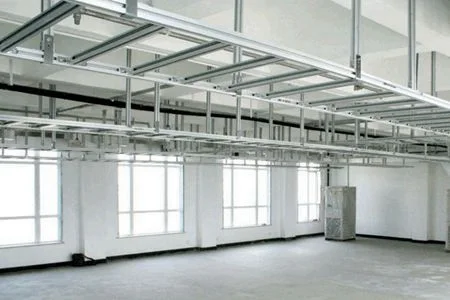
Busway (busbar trunking) is used where power routes must stay clean, expandable, and easy to maintain — especially in long corridors, technical spaces, and facilities with changing loads.

Busway trunking route in a utility tunnel for long-run power distribution and maintenance access

Utility Tunnel

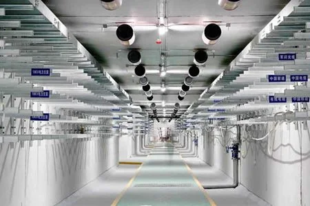
A structured busway route keeps long tunnel distribution predictable and serviceable for inspections and upgrades.

Busway system in a data center for expandable overhead power distribution and fast equipment additions

Data Center

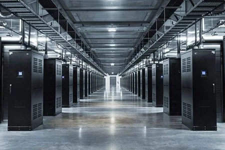
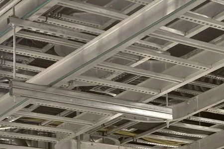
Busway supports expandable power distribution with clear routing and optional tap-off points for new racks and rooms.

Busway system in a distribution station for organized power routes between switchboards and equipment rooms

Distribution Station

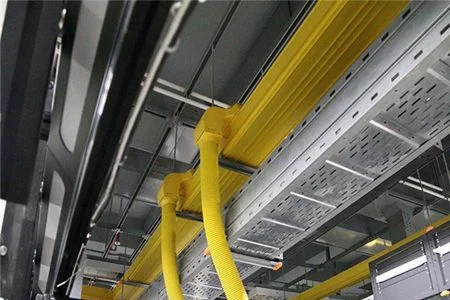
Used between switchboards and load areas to keep feeder routes clean, documented, and easier to maintain than large cable bundles.

Busway system installed in a factory workshop for flexible distribution to production equipment

Factory Workshop

Ideal for production lines with changing layouts — add tap-off feeds without rebuilding the main trunk route.

Busway trunking in a metro tunnel for reliable long-run power distribution and inspection-ready routing

Metro Tunnel

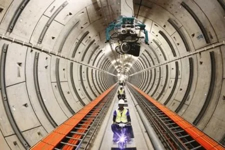
For transit tunnels, defined trunk sections and joints make long-run distribution easier to plan, install, and service.

Busway system used in transport infrastructure for scalable power distribution pathways and maintenance

Transport Infrastructure

Suitable for large facilities where scalable distribution routes and maintenance access are critical across long corridors and zones.

Manufacturing & QC

Manufacturing Process
& Quality Control for Busway

Busway performance is decided by conductor preparation, insulation integrity, and joint consistency. We control the process to keep sections, joints, and tap-off interfaces installation-ready.

01
Material Control

Conductor & Housing Preparation

Select conductor material (Copper / Aluminum) and housing structure. Confirm rating intent and installation environment before section design is locked.

Cu / Al Structure Project Match
02
Insulation Build

Insulation & Clearance Control

Apply insulation system and maintain clearance/creepage intent inside the enclosure so the trunking remains stable under load.

Insulation Clearance Consistency
03
Section Forming

Trunking Section Assembly

Build straight sections and standard parts with controlled alignment, so field installation stays predictable for long corridors.

Straight Alignment Modular
04
Joint System

Joint Pack & Interface Control

Joint consistency is critical. We control contact interface condition and assembly repeatability to reduce site ambiguity.

Joint Interface Repeatable
05
Testing

Routine Checks Before Packing

Verify assembly integrity and section readiness prior to delivery so receiving and installation can follow a clear sequence.

Routine Traceable Ready-to-Install
06
Delivery

Packing & Project Staging

Section labeling and packing logic help site teams stage trunking, elbows, and accessories efficiently—reducing rework on arrival.

Labeling Staging Site Workflow

Ready to Confirm Your Busway System Takeoff?

Share your SLD and route plan (length / elbows / risers), current rating and installation environment. We’ll help validate the section schedule, tap-off plan, and deliver a project-ready BOM for fast quotation and site-ready installation.

View Cable Tray Systems

Busway (Busduct) FAQ

Common questions about electrical busway (also called busduct / busbar trunking): selection, tap-off strategy, installation planning, and compliance considerations.

01.

What is a busway (busduct) in electrical distribution?

An electrical busway is a prefabricated power distribution system made of enclosed conductors (busbars) inside a metal housing. It is assembled from straight sections, joints, elbows/offsets, and end feeders—providing a clean, modular alternative to large cable bundles.
02.

What are other names for busway?

Common terms include busduct, busbar trunking, busbar trunking system, and sometimes simply busbar system. In practice, “busway” and “busduct” are often used interchangeably.
03.

How does a busduct work?

Power flows through the internal busbars across each section-to-section joint. A feeder unit connects the busway to the source (switchboard/transformer), and loads are supplied either by an end termination or via tap-off points using plug-in boxes.
04.

What are the main types of busway systems?

From a project perspective, the most practical split is feeder busway (fixed runs, no tap-off points) vs plug-in busway (tap-off points for flexible distribution). Systems are also selected by current rating, IP protection, and installation environment.
05.

What is a tap-off unit and why is it important?

A tap-off unit (plug-in box) is a localized takeoff point that connects to a busway tap-off opening to feed downstream loads. It enables staged expansion and load changes without rerouting long cable runs—especially useful for workshops, production lines, and data halls.
06.

Busway vs cable tray: what’s the difference?

Cable tray is a support pathway for cables; busway is a prefabricated power conductor system. If you need modular high-current distribution with clean routing and fast expansion (tap-off), busway is often preferred. If your scope is mixed cabling (power + control + data) and flexible segregation, cable tray may be the better base infrastructure.
07.

What determines copper vs aluminum busbar selection?

Copper is typically chosen for compactness and lower resistance at the same current, while aluminum can reduce material cost and weight. The final decision should consider current rating, temperature rise limits, installation space, budget, and the project’s connection/joint strategy.
08.

What are common problems with busduct systems?

Most issues are installation-related: incorrect joint torque/assembly, poor alignment at offsets, missing bonding continuity, or moisture ingress beyond the system IP level. A clear route plan + section schedule + support layout is the best prevention.
09.

How long does a busway typically last?

Service life depends on thermal loading profile, environment (humidity/corrosion/dust), joint quality, and maintenance practices. In stable indoor conditions with correct installation, busway is commonly treated as long-life building infrastructure.
10.

Which standard defines busway requirements (NEC)?

In the U.S., busway is addressed under the National Electrical Code (NEC), commonly referenced via NFPA 70. For project compliance, confirm the applicable NEC article and local AHJ requirements. Reference: NFPA 70 (NEC).