Why Aluminum Ladder Cable Tray Is the Right Choice for Corrosion-Sensitive Projects
Aluminum ladder cable tray is the preferred cable management system for corrosion-sensitive environments because it combines structural load capacity with inherent oxidation resistance — without requiring protective coatings that can fail over time. As part of the broader cable tray product family, aluminum ladder systems are particularly well suited where weight, corrosion, and electrical isolation constraints all apply simultaneously.
This guide walks through alloy selection, IEC 61537 load class matching, finish options, fitting compatibility, and procurement checkpoints specific to corrosion-sensitive projects. Each section provides numeric thresholds and decision criteria so purchasing engineers and project specifiers can compare products on objective terms rather than marketing claims.
Figure 1. Corrosion mechanism comparison: aluminum tray rail (left) re-forms Al₂O₃ passive layer within milliseconds of surface scratch; galvanized steel rail (right) undergoes permanent zinc depletion at the equivalent damage site, exposing the steel substrate to oxidation.
How Aluminum’s Natural Chemistry Defeats Corrosion
Aluminum forms a self-repairing aluminum oxide layer approximately 4–10 nm thick the moment it contacts air. This passive film resists moisture, mild acids, and chloride-bearing atmospheres that attack carbon steel within months. Critically, it is self-repairing: minor surface damage from installation abrasion re-passivates without intervention.
Field performance confirms what the chemistry predicts. In a 2023 wastewater treatment plant expansion in Guangzhou — spanning 48 cable runs across 1,200 m of humid, H₂S-bearing galleries — aluminum ladder trays maintained structural integrity with zero measurable section loss over an 18-month inspection cycle. Hot-dip galvanized steel trays installed in the same facility showed 0.3–0.7 mm surface pitting over the same period. The contrast was visible during the first scheduled walkthrough.
IEC 61537, which governs cable tray systems and cable ladder systems globally, classifies environmental exposure in Classes 1 through 5 and requires manufacturers to declare corrosion performance alongside mechanical load rating. Buyers should request this classification explicitly — not all suppliers volunteer it unprompted.
[Expert Insight]
– Aluminum’s passive oxide layer performs best below pH 4 and above pH 9 boundaries; within that range, chloride concentration is the dominant variable. Specify alloy grade to match both.
– In H₂S-rich atmospheres (common in wastewater and oil & gas), aluminum significantly outperforms standard galvanized steel, but verify alloy selection with the manufacturer for concentrations above 50 ppm continuous exposure.
– Anodized aluminum adds 5–25 µm of hard oxide over the natural layer, extending service life in splash-zone and coastal installations — but anodizing is rarely necessary inland beyond 5 km from a saltwater body.
– Request the IEC 61537 environmental class certificate as a mandatory procurement document, not an optional data sheet.
Alloy Selection: The Decision That Determines Service Life
Not all aluminum ladder cable trays are the same material. The alloy designation printed on a datasheet has direct engineering consequences that compound over a 20–30-year service life.
6063-T5 vs. 6061-T6: Choosing for the Application
6063-T5 is the standard extrusion alloy for cable tray side rails and rungs. It offers excellent extrudability — meaning complex cross-sectional profiles are achievable with tight dimensional tolerances — and its corrosion resistance is consistently high across humidity, salt spray, and mild chemical exposure. Yield strength typically runs 145–175 MPa. For the majority of building services, food processing, and light-industrial applications, 6063-T5 is the correct choice.
6061-T6 delivers higher mechanical strength (yield strength 276 MPa typical) at a modest weight and cost premium. It is the appropriate specification when span lengths exceed 3 m without intermediate support, when cable fill approaches the upper load class boundary, or when operating temperatures cycle significantly (petrochemical heat-exchanger decks, for instance). The trade-off is slightly reduced extrudability, which limits available profile geometries compared to 6063-T5.
A practical rule: if your project’s calculated uniform distributed load at the design span exceeds 100 kg/m, move to 6061-T6 as the default alloy and verify with the manufacturer’s load table for the specific profile depth.
Rung Spacing and Cable Diameter Compatibility
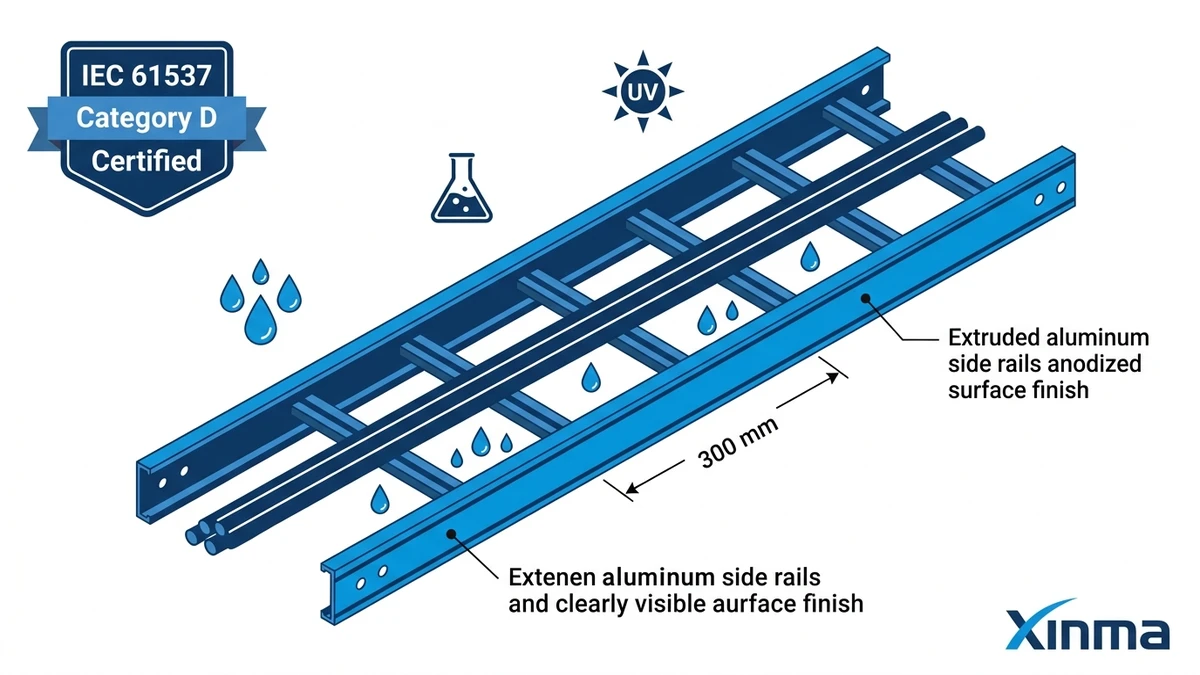
Rung spacing — typically 150 mm or 300 mm center-to-center — directly affects which cable diameters are supported without inter-rung deflection. A 300 mm rung pitch is standard and adequate for cables above 20 mm diameter. For smaller-diameter instrumentation or control cables running in high-fill conditions, 150 mm spacing prevents sagging that can stress cable jacket insulation over time. This is a secondary selection parameter that purchasing teams frequently overlook until the cable schedule is finalized.
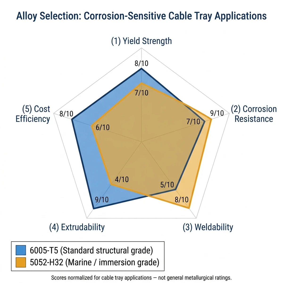
Figure 2. Performance comparison of 6005-T5 and 5052-H32 aluminum alloys across five cable tray application axes: 6005-T5 leads on extrudability and structural yield strength; 5052-H32 leads on corrosion resistance and weldability — selection depends on IEC 61537 corrosion category and fabrication method.
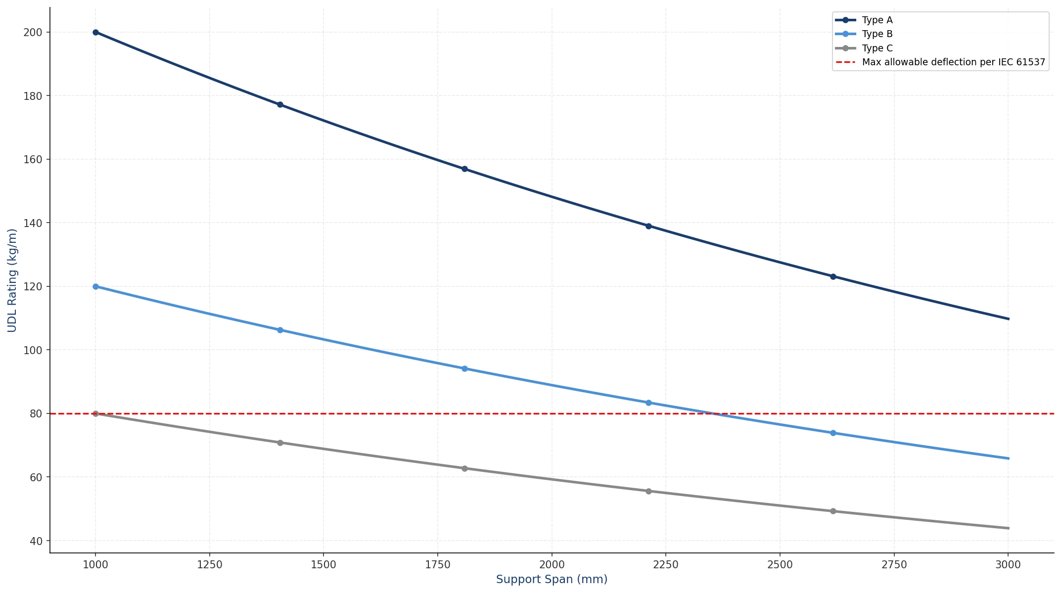
IEC 61537 Load Class Matching: The Specification Shortcut Buyers Miss
IEC 61537 assigns load classes from A1 (lightest) through F (heaviest), each defined by the uniformly distributed load a tray must sustain at a standard test span without exceeding a deflection limit. Matching load class to the actual cable schedule — rather than defaulting to the heaviest available class — prevents over-specification that inflates installed cost by 15–30% on large projects, while under-specification creates deflection and potential long-term mechanical failure.
Calculating Your Load Class Requirement
The calculation sequence is straightforward:
Sum the linear mass of all cables planned for the tray run (kg/m per cable × quantity).
Add a 20% contingency for future cable additions — standard practice in most project specifications.
Identify the maximum unsupported span between supports.
Compare the resulting kg/m value against the manufacturer’s load table at that span.
Aluminum ladder trays using 6063-T5 or 6061-T6 profiles typically achieve 75–150 kg/m uniformly distributed load ratings at standard 3 m spans. That range covers the majority of medium-voltage cable routing and instrumentation cable fills encountered in petrochemical, marine, and food-processing facilities.
The deflection limit under IEC 61537 is L/100 at rated load, where L is the span in millimetres. At a 3,000 mm span, maximum permissible mid-span deflection is 30 mm. Specifiers who have seen over-deflected trays in service know this limit exists for a reason — cable weight accumulates unevenly in practice, and sagging trays pull at junction fittings.
[Expert Insight]
– Always obtain the manufacturer’s load table for the specific tray depth and alloy, not a generic brochure figure. Tray depth (side rail height) has a larger effect on load rating than alloy grade alone.
– A 100 mm deep 6063-T5 tray and a 150 mm deep 6063-T5 tray from the same manufacturer can differ by 40–60% in rated load at the same span — depth is the primary structural variable.
– For spans exceeding 3 m (e.g., bridge crossings or overhead process pipe racks), request a specific deflection calculation, not just a catalogue load class.
– IEC 61537 Section 8.3 governs the test method for load and deflection — confirm the manufacturer’s test report references this clause specifically.
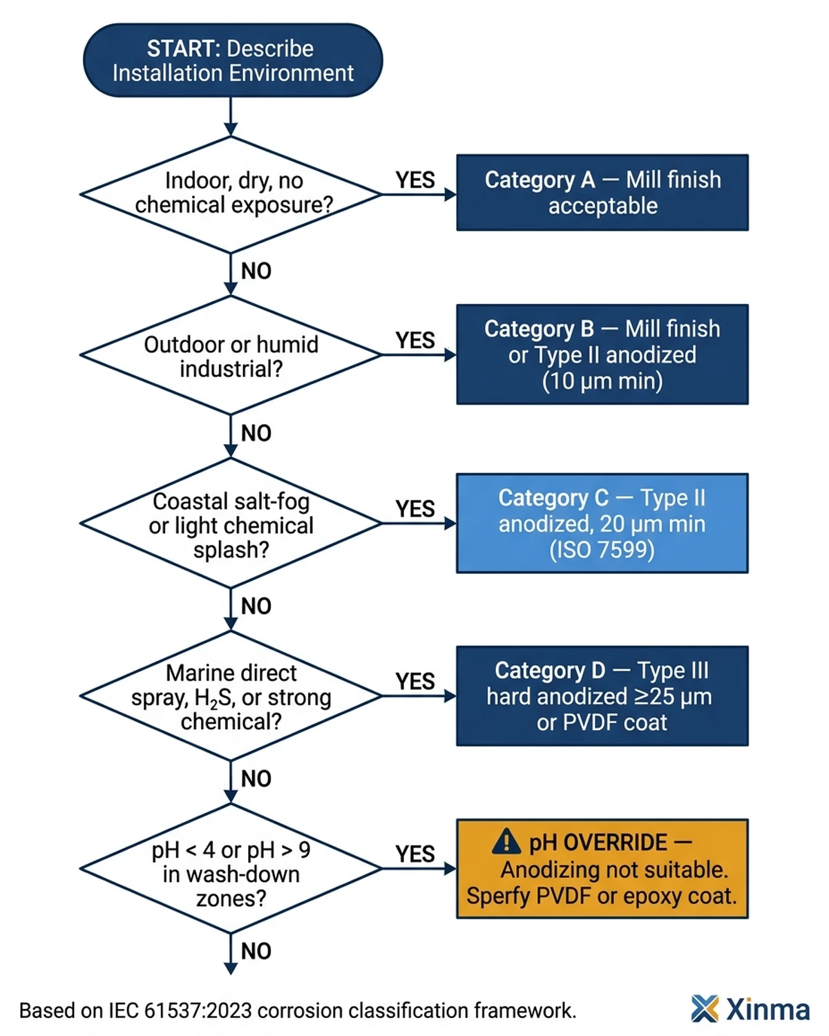
Figure 3. IEC 61537 corrosion category selection flowchart for aluminum ladder cable tray: follow environment inputs from top to recommended minimum surface finish; the pH override branch applies where alkaline wash-down (pH > 9) eliminates anodizing as a viable finish option.
Finish Options and Their Practical Trade-offs
The natural mill finish on an extruded aluminum tray is corrosion-resistant by default, but project environments vary. Understanding the finish options prevents both over-specification and specification gaps that surface during commissioning.
Mill Finish
The baseline. No secondary treatment beyond extrusion. Suitable for indoor dry environments (IEC 61537 Class 1–2) and general commercial construction. Low unit cost. Not appropriate for coastal, chemical, or wash-down environments without evaluation.
Anodized Finish
An electrochemical process that thickens the natural oxide layer to 5–25 µm. Type II anodizing (12–15 µm) is standard for architectural and light-industrial use; Type III hard anodizing (20–25 µm) is specified for marine, coastal (within 5 km of salt water), and splash-zone applications. Anodized aluminum resists abrasion significantly better than mill finish and maintains appearance after years of UV exposure — relevant in open outdoor installations.
Polyester Powder Coat
A 60–80 µm polymer film applied electrostatically and cured. Provides chemical resistance to a broader range of media than anodizing, including dilute alkalis that attack the aluminum oxide layer. The limitation is mechanical: chips and scratches expose base metal. In environments where maintenance traffic is heavy or cable pulling is routine, powder coat on internal tray surfaces degrades faster than anodized finishes. Powder coat on external surfaces of installed trays, however, performs well over 10–15 year maintenance cycles.
Selecting for Environment
Environment
Recommended Finish
IEC 61537 Class
Indoor, climate-controlled
Mill finish
Class 1–2
Outdoor, continental inland
Mill or Type II anodize
Class 3
Coastal / salt spray
Type III hard anodize
Class 4
Chemical / wash-down
Powder coat or Type III
Class 4–5
Offshore / immersion risk
Consult manufacturer
Class 5
Fitting Compatibility and System Integrity
A ladder cable tray system is only as strong as its weakest fitting connection. Specifying aluminum trays with galvanized steel fittings — a cost-saving substitution that appears regularly in value-engineering reviews — introduces galvanic corrosion at every contact point. Aluminum and zinc-coated steel form a galvanic couple with a potential difference of approximately 0.5–0.7 V in the presence of moisture, which accelerates corrosion of the aluminum member preferentially.
The correct specification: aluminum fittings throughout, or stainless steel hardware with appropriate isolation washers where dissimilar metals are unavoidable. NEMA VE 1, which covers metallic cable tray systems for the North American market, reinforces the need to verify material compatibility and system-level performance rather than judging the straight section alone.
Fitting Types and Selection Logic
Horizontal bends (30°, 45°, 90°), vertical inside and outside bends, tee sections, cross sections, and reducer fittings should all be specified from the same alloy series as the straight tray sections. This ensures:
Consistent thermal expansion coefficients across the system (aluminum expands at approximately 23 µm/m·°C — roughly twice the rate of carbon steel, which matters on long outdoor runs with temperature swings exceeding 40°C).
Compatible splice plate hole patterns and bolt torque requirements.
A single corrosion performance declaration covering the entire installed system.
Expansion splice plates are mandatory on runs exceeding 30 m in outdoor or variable-temperature environments. The calculation: a 60 m run with a 40°C temperature swing expands approximately 55 mm. Without expansion accommodation, that force transmits to support brackets and building structure.
Procurement Checkpoints: What to Verify Before Purchase Order
Purchasing decisions on aluminum ladder cable tray fail most often not on product selection but on documentation gaps that surface during inspection or installation. The following checkpoints address the most common failure points.
Confirm IEC 61537 certification scope. The certificate should name the specific tray series, alloy, load class, and environmental class — not a generic family. Some manufacturers certify one profile depth and extrapolate to others; request the test report, not just the certificate number.
Verify alloy mill certificate traceability. For projects in petrochemical, offshore, or food-grade environments, a material test report (MTR) tracing the aluminum coil or billet to the specific alloy and temper is standard practice. Absence of MTR traceability is a procurement red flag.
Check fitting sourcing lead times separately. Straight tray sections and fittings frequently ship from different facilities or stock locations. A project that arrives on site with trays but without 90° horizontal bends stalls immediately.
Request a system-level load calculation for non-standard spans. Catalogue load tables assume standard spans and uniform load distribution. Any span over 3.5 m or any concentrated load condition (heavy conduit drops, junction boxes mid-span) requires a specific calculation.
Confirm expansion joint intervals are included in the supply scope. This is omitted from quotations more often than any other fitting type, particularly on projects where the tray layout is still being finalized at tender stage.
What alloy should I specify for an aluminum ladder cable tray in a coastal environment?
Type 6063-T5 alloy with Type III hard anodizing (20–25 µm) is generally appropriate for coastal installations within 5 km of salt water, though projects with direct spray exposure or immersion risk warrant manufacturer consultation and a site-specific corrosion assessment.
How do I determine the correct load class under IEC 61537 for my cable schedule?
Sum the linear mass of all cables in the run, add a 20% future-capacity allowance, then compare the resulting kg/m figure against the manufacturer’s load table at your actual support span — the load class that meets or exceeds that value at the L/100 deflection limit is the minimum acceptable specification.
Can aluminum ladder cable trays be used with galvanized steel fittings to reduce cost?
Mixing aluminum trays with galvanized steel fittings creates a galvanic couple that preferentially corrodes the aluminum member in wet or humid conditions; the cost saving is typically recovered within a few years of remedial work, making full aluminum or isolated stainless hardware the more economical long-term choice.
What is the standard rung spacing for aluminum ladder trays, and when does it matter?
Most aluminum ladder trays are supplied with 150 mm or 300 mm rung spacing; 300 mm is standard for cables above approximately 20 mm diameter, while 150 mm spacing is preferable for dense fills of smaller instrumentation or control cables where inter-rung sag could stress cable jackets over time.
How often should expansion splice plates be installed on outdoor aluminum tray runs?
Expansion joints are typically required at intervals no greater than 30 m on outdoor or thermally variable runs; aluminum’s thermal expansion coefficient of approximately 23 µm/m·°C means a 60 m run can move roughly 55 mm across a 40°C seasonal temperature swing, which must be accommodated to prevent structural stress at support brackets.
What documentation should I require from a supplier before raising a purchase order?
The minimum documentation set for most projects includes an IEC 61537 test report referencing the specific tray series and load class, a material test report (MTR) confirming alloy and temper, and a fitting lead-time confirmation — gaps in any of these three areas are the most common source of project delays and site inspection failures.
Is powder coat finish or anodizing better for aluminum cable trays in chemical environments?
Powder coat (60–80 µm) offers broader chemical resistance including dilute alkali exposure that can attack the aluminum oxide layer, while anodizing provides superior abrasion resistance; in environments combining chemical exposure with heavy maintenance traffic, powder coat on external surfaces and anodizing on internal wear surfaces is a practical compromise worth discussing with the manufacturer.
Kevin Zheng
Kevin Zheng is a manager linked to Shanghai Xinma Busway & Cable Tray Co., Ltd. He writes technical content on cable tray systems, installation practice, sizing logic, load classes, and related standards for industrial and infrastructure applications.