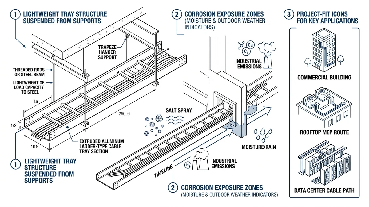
Aluminum cable tray is a metal cable management system used to support and route power, control, and data cables where low dead load and good atmospheric corrosion resistance matter. In many projects, it weighs about 30% to 50% less than comparable steel systems, but selection still depends on tested span, deflection, fittings, bonding, and environment—not material name alone. IEC 61537 is the key tray-system standard because it evaluates tray performance as an installed system, including load, support conditions, and deflection.
That matters in practice. A tray that works at a 3.0 m span may not keep the same margin if support spacing, fittings, covers, or cable fill change. The real question is not “Is aluminum better than steel?” but “Does aluminum fit this run’s loading, corrosion exposure, access, and coordination constraints?”
Aluminum cable tray is often a good fit for rooftops, indoor industrial areas, wastewater-adjacent spaces, and retrofit runs where hanger capacity or manual handling is limited. It is less forgiving where chloride deposition, heavy impact, or very high fault-duty mechanical forces govern the design.
How Does Aluminum Cable Tray Change Structural Loading and Handling?
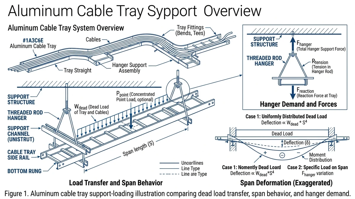
Aluminum cable tray reduces permanent load on the support system, but that does not automatically allow longer spans or lighter-duty supports. Its main value is lower hanger reaction, easier field handling, and less cumulative building load over long runs.
What changes in structural loading
The key number is total distributed load in kg/m: tray self-weight + cable weight + covers + dividers + splice hardware + accessories. For a 300 mm ladder tray, aluminum may weigh about 3 kg/m to 6 kg/m, while a comparable steel tray may weigh 6 kg/m to 10 kg/m.
Why lighter does not mean stiffer
Aluminum has an elastic modulus of about 69 GPa, versus roughly 200 GPa for carbon steel, so the same profile usually deflects more under load. Under IEC 61537, span and load class must follow the tested tray configuration rather than weight alone.
Worked design example
Assume a run carries 40 kg/m of cables over a 3.0 m span; if the aluminum tray weighs 4 kg/m and the steel tray weighs 8 kg/m, total distributed load changes from 48 kg/m to 44 kg/m. That is only an 8.3% reduction, which shows that cable mass often dominates and spacing still tends to be set by deflection and fittings rather than tray material.
Design use:
– Use when: dead load, rooftop support limits, or overhead access are constraints.
– Avoid when: span is being pushed primarily for stiffness rather than weight.
– Check before specifying: tested load/span table, midspan deflection, side rail depth, and accessory weight.
Figure 1. Aluminum cable tray support-loading illustration comparing dead load transfer, span behavior, and hanger demand.
Is Aluminum Cable Tray Actually Corrosion Resistant?
Yes, but only when matched to the environment. Aluminum resists many atmospheric exposures because it forms a thin oxide film that slows further attack, but that film can break down in chloride-rich, highly alkaline, or chemically aggressive settings. The right question is not whether aluminum corrodes, but how it corrodes in the actual service chemistry.
The mechanism that matters
Aluminum usually does not fail by broad rusting like unprotected carbon steel. The main risks are localized attack such as pitting under deposits, crevice corrosion at joints, and galvanic attack at wet dissimilar-metal interfaces.
Galvanic compatibility is often the hidden failure point
Under IEC 61537, the tray system has to be considered as installed, not as bare metal. Fasteners, splice plates, supports, grounding lugs, and wet contact points often govern early deterioration more than the straight tray sections.
Design consequence for project selection
Aluminum cable tray is a strong fit where the tray can dry between wetting cycles and where deposits can be inspected and removed. It is a weaker fit where the route stays wet, salt-laden, or chemically contaminated during normal operation.
Use this decision logic:
– Use when: exposure is atmospheric, drainage is good, and maintenance access is realistic.
– Avoid when: direct saline washdown, severe chemical attack, or persistent wet deposits are expected.
– Check before specifying: dissimilar-metal interfaces, joint details, cleaning access, and inspection interval.
[Expert Insight]
– Chlorides are usually more damaging when they remain as deposits than when exposure is only occasional airborne mist. Design for wash-off and drainage, not just nominal material resistance.
– Covered tray can reduce contamination, but it may also trap moisture and debris. Use covers only when inspection and cleaning access remain practical.
– In mixed-metal support systems, isolate the detail that stays wet the longest. That interface often controls service life.
Figure 2. Environment suitability matrix showing where aluminum cable tray is a strong, conditional, or weak fit.
Aluminum vs Steel Cable Tray: Which Trade-Offs Matter Most?
The real comparison is a system trade-off among dead load, stiffness, corrosion behavior, handling, abuse resistance, and installed consequence. Aluminum usually reduces support loading and corrosion maintenance, while steel offers better stiffness and impact tolerance for the same profile.
Engineering comparison table
Parameter
Aluminum cable tray
Steel cable tray
What it means in design
Density
About 2,700 kg/m³
About 7,850 kg/m³
Aluminum imposes much lower dead load on overhead supports
Elastic modulus
About 69 GPa
About 200 GPa
Steel is generally stiffer for the same geometry and load
Corrosion behavior
Stable oxide film in many atmospheres
Bare carbon steel corrodes quickly; coatings become critical
Environment may dominate first-cost decisions
Impact tolerance
Good, but easier to dent
Better under rough handling and point abuse
Low-mounted or congested routes often favor steel
Span sensitivity
More sensitive to stiffness-related deflection
Usually more forgiving at equal geometry
Aluminum often needs closer span/load validation
Magnetic behavior
Non-magnetic
Ferromagnetic for carbon steel
Aluminum can help with single-core AC cable routing concerns
Maintenance burden
Often lower in mild corrosive exposure
Coating damage requires follow-up
Outdoor steel routes may need more coating inspection
Material cost basis
Often higher per kg
Often lower per kg
Installed cost may reverse once support steel and corrosion measures are included
What usually decides the choice
For a 300 mm tray carrying 40–60 kg/m of cables, both materials may work at a 2.0 m span. The choice usually follows the governing limit: steel when deflection margin or impact resistance dominates, aluminum when support loading or atmospheric corrosion maintenance dominates.
Use when / avoid when / check before specifying
Use aluminum cable tray when: the project benefits from lower dead load, non-magnetic behavior, and lower atmospheric corrosion maintenance.
Avoid aluminum cable tray when: severe impact, direct saline washdown, or stiffness-limited long spans control the design.
Check before specifying: tested span-load class, side rail geometry, support spacing, bonding detail, and corrosion compatibility at fittings.
For broader system comparison across tray forms, Xinma’s overview of cable management applications is useful when the route includes mixed power and control services, while the aluminum and steel ladder tray options help frame stiffness versus access trade-offs at the product level.
What Projects Are a Good Fit for Aluminum Cable Tray?
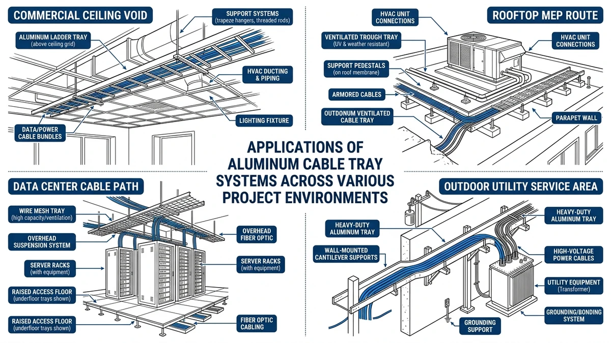
Aluminum cable tray fits best where low dead load, moderate mechanical duty, and environment-driven durability matter more than maximum impact strength. Typical examples include long elevated runs, rooftops, utility plants, and retrofits with limited structural reserve.
Best-fit project types
Project fit is easier to judge by route condition than by industry label. Aluminum is often well suited to rooftop runs, retrofit mezzanines, humid utility spaces, moderate-load instrumentation routes, and single-core AC cable layouts where non-magnetic support hardware is useful.
Where aluminum is less suitable
Aluminum is less attractive where the route sees regular mechanical abuse, forklift strike exposure, very high short-circuit mechanical demands, concentrated heavy power cable loading, or direct chemical washdown and salt splash. In those cases, steel may offer better robustness, while FRP may fit severe chemical environments better.
Practical selection consequence
If the route is overhead, access is difficult, and the environment is mildly to moderately corrosive, aluminum often improves the overall cable management system. If the route is low, heavily loaded, and physically exposed, its weight advantage may not offset impact and stiffness penalties.
For route planning, support spacing, and size coordination, specifiers often cross-check tray form against width and loading using Xinma’s tray sizing reference and the broader cable tray product range.
Figure 3. Application-fit map linking aluminum cable tray selection to route conditions and maintenance realities.
Which Engineering Checks Should Come Before Specification?
Before specifying aluminum cable tray, verify five items together: load and span, corrosion exposure, bonding path, cable thermal condition, and installation access. Many specification problems start when width is chosen from cable count alone.
Verify tray loading and allowable span
Calculate total uniformly distributed load in kg/m, including tray, cables, covers, dividers, and hardware. Then compare that load with the tested span data for the actual tray series, since a route carrying 45 kg/m of cables plus 8 kg/m of tray and fittings can require a different support layout at 3.0 m than at 1.5 m.
Check corrosion exposure before choosing alloy and hardware
Identify whether the route sees chlorides, alkaline runoff, fertilizer dust, cement washdown, or long-term condensation. Corrosion problems usually start at transitions such as cut edges, hardware joints, and support clamps, so fasteners and isolation details matter as much as base alloy.
Confirm electrical bonding and fault-current path
If the aluminum cable tray is intended to contribute to equipment bonding, continuity across couplers and fittings must align with the governing code and manufacturer test data. IEC 61537 includes electrical continuity characteristics for tray systems, and the IEC 61537 publication page is the right starting point for system-level validation.
Review cable fill, separation, and thermal derating
Tray width is not just a cable count; it must also allow bending radius at direction changes, service segregation, future fill margin, and heat dissipation. On rooftops or covered runs, ambient temperatures may exceed 40 °C, so ampacity derating and a 20% to 30% growth margin can affect tray choice.
Check installation constraints and maintenance access
Review route geometry, support attachment points, access intervals, seismic restraint, and thermal movement. Long outdoor runs may need expansion provisions, and practical detailing can be coordinated using Xinma’s support layout guidance and fittings and connection hardware.
[Expert Insight]
– A tray schedule that ignores cover weight can understate distributed load enough to change support spacing on long rooftop runs.
– If future cable growth is likely, adding width early is usually easier than increasing side rail depth after supports are already fixed.
– Bonding strategy should be agreed before procurement. Retrofitting jumpers around incompatible joints is possible, but it usually costs more and complicates inspection.
How Xinma Helps Coordinate Loading, Corrosion, Fittings, and Access Planning
Aluminum cable tray should be specified as a coordinated system, not as a stand-alone material line. The engineering task is to align tray width, side rail depth, alloy choice, fittings, supports, and access requirements so the installed route still meets load, corrosion, and maintenance expectations.
What should be checked together
A tray rated at 75 kg/m over a 3.0 m span can lose usable margin once covers, dividers, hold-down hardware, and concentrated loads at bends are added. Straight lengths may satisfy the load table, but fittings, splice locations, and corrosion details often govern actual performance.
Where technical support is most useful
Xinma can help evaluate tray loading versus support spacing, continuity across fittings, corrosion exposure versus hardware choices, and access planning for covers and future cable additions. That support is most useful while the specification is still balancing structural loading, environment, bonding, and maintenance reality.
Frequently Asked Questions
Is aluminum cable tray strong enough for heavy power cable runs?
It can be, but only if the tested load class, support span, and tray geometry match the cable load. On heavily loaded routes, stiffness and deflection often become the deciding factors rather than base material alone.
Does aluminum cable tray rust like steel?
It does not rust in the same way as carbon steel because it forms a protective oxide layer. The more common concern is localized pitting or galvanic attack in wet, contaminated, or chloride-rich environments.
When is steel cable tray a better choice than aluminum?
Steel is often the better option where the tray may see impact, concentrated abuse, or long spans controlled by stiffness. It can also be preferred when fault-duty mechanics or low-mounted industrial exposure dominate the design.
Can aluminum cable tray be used outdoors?
Yes, in many outdoor conditions it performs well, especially where drainage is good and contamination can be inspected. Outdoor coastal or chemical exposure usually needs a closer review of deposits, hardware compatibility, and maintenance access.
How do I size aluminum cable tray for future expansion?
Start with the present cable schedule, then add a realistic reserve margin—often around 20% to 30% if future additions are likely. That margin should be checked against fill, bending space at fittings, and the support load that wider tray sections create.
Does aluminum cable tray need special bonding checks?
Usually yes, especially if the tray is intended to contribute to the equipment bonding path. Joint continuity, splice hardware, and possible fault-current duty should be verified before final specification.
What should I inspect first on an existing aluminum cable tray installation?
Look first at joints, support interfaces, cut edges, and areas where deposits stay wet. Those locations tend to reveal galvanic issues, trapped contamination, or early localized corrosion before the straight runs do.
Kevin Zheng
Kevin Zheng is a manager linked to Shanghai Xinma Busway & Cable Tray Co., Ltd. He writes technical content on cable tray systems, installation practice, sizing logic, load classes, and related standards for industrial and infrastructure applications.