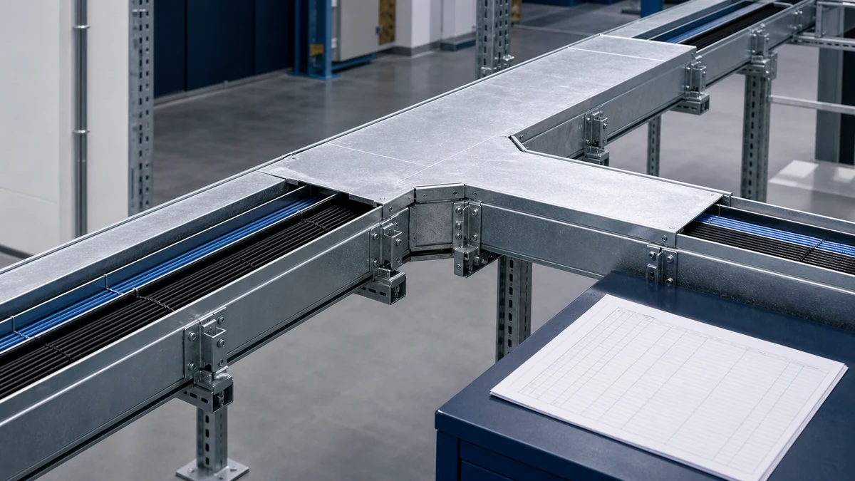
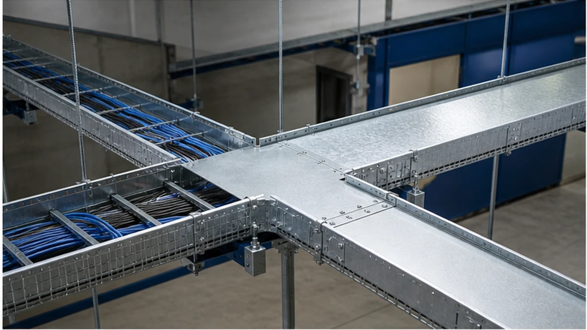
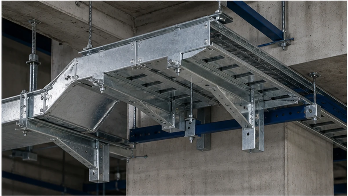
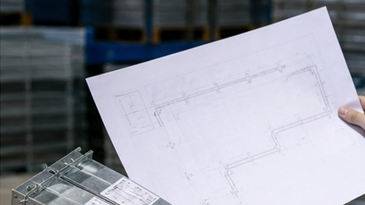
Cable tray weight calculation is a route-level quantity exercise. The load presented to a support or structure includes more than the empty straight tray: fittings, covers, dividers, splice hardware, supports, cable cleats, the installed cable assembly, and provisions for future additions can all contribute. Steel and aluminum systems use different profiles, finishes, accessories, and connection details, so a generic weight-per-metre figure is not a safe substitute for an approved model-specific takeoff.
The workflow below covers route-level quantity takeoff, model-data sourcing, straight-section versus fitting treatment, cable and future-load assumptions, support handoff, and handling and receiving controls. Begin by defining the selected cable tray system and confirming the current route drawing revision before any quantities are entered.
Cable tray load inputs
Build the Calculation from Approved Product Data
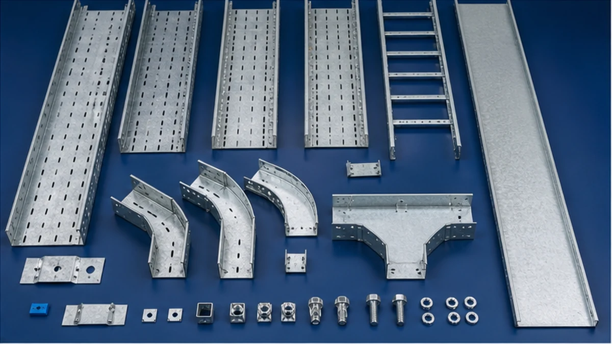
For each tray item, use the supplier’s current published data for the exact material, width, depth, length, finish, and model code. List straight sections separately from elbows, tees, crosses, reducers, risers, drops, splice plates, covers, dividers, and any special transition pieces. Multiplying one straight-section value across a route that contains numerous fittings or nonstandard components will produce an unreliable result.
Identify the cable groups assigned to each route segment from the approved cable schedule. Cable quantity, outside diameter, construction type, and route occupancy can change the installed load materially between segments. Include only the allowance that the responsible design team has approved and documented; do not classify every empty portion of a tray as future load without a recorded project requirement.
IEC 61537 provides a reference framework for cable tray and cable ladder systems. Apply it in the product-system context appropriate to the project, then have the responsible structural and electrical designers confirm the governing load case, support design, and installation requirements before the takeoff is issued for construction.
Separate Material, Accessories, and Cable Load Entries
Create distinct line items for tray material, accessories, cables, and any project-defined future allowance. Keeping these separate makes changes visible and auditable. A switch from galvanized steel to aluminum, a change in cover extent, a revised divider layout, a different cable grouping, or a fitting count correction should update the calculation in a traceable way rather than be absorbed into a single route total.
The table structure below illustrates a route-level weight-takeoff format. Populate each field from approved model data; do not carry forward assumed values from a previous project or a different tray family.
Route segment
Item type
Model code
Material
Qty
Unit mass (supplier data)
Extended mass
Notes
Segment A
Straight section
—
—
—
From supplier
—
Drawing rev.
Segment A
Elbow fitting
—
—
—
From supplier
—
Drawing rev.
Segment A
Cover
—
—
—
From supplier
—
Drawing rev.
Segment A
Cable group 1
—
—
—
From cable schedule
—
Schedule rev.
Segment A
Future allowance
—
—
—
Design-approved only
—
Ref. document
For ladder cable tray routes, include the exact rung and rail profile plus any cable-support or cover components specific to that system. For perforated routes, confirm the perforated cable tray section, matching fittings, and attachment hardware. A product family page helps identify the system, but the final quantity must come from approved model-level data rather than a family average.
Cable tray weight BOM
Straight Sections Versus Fittings and Accessories
Straight sections and fittings behave differently in a takeoff. A straight section has a predictable mass per unit length that scales with the quantity ordered. Fittings — elbows, tees, crosses, reducers, and transition pieces — each carry a discrete mass that does not scale with run length, and they often concentrate at locations where support conditions also change.
Accessories including covers, dividers, splice plates, cable cleats, and earthing straps add mass that may be distributed differently from the tray sections themselves. A fully covered section with internal dividers can differ substantially from an open ladder run of the same width and length. Treat each accessory category as a separate line in the takeoff and confirm that the model codes used for accessories are compatible with the selected tray series.
The checklist below identifies common items that are omitted from early-stage estimates:
Radius elbows and flat elbows at direction changes
Vertical inside and outside bends at elevation changes
Tee and cross fittings at branch points
Reducers at width transitions
End caps and closure plates
Splice plates and associated hardware at section joints
Cover sections, cover clips, and cover hold-down hardware
Internal dividers and divider support brackets
Cable cleats and tie-down accessories
Earthing continuity straps and bonding hardware
Seismic-bracing attachment points where required
Each item on this list carries a discrete mass from the supplier’s data sheet. Confirm that the data sheet revision matches the model code on the approved drawing.
Cable and Future-Load Assumptions
Cable load is typically the largest variable in an installed tray weight calculation. The mass per metre of a cable group depends on conductor size, insulation type, armoring, sheathing, and the number of cables in the group. Obtain these values from the approved cable schedule and the cable manufacturer’s data; do not estimate from conductor cross-section alone.
Route occupancy — the proportion of tray width and depth occupied by cables — affects both the cable load and the applicable future allowance. If the project specifies a future-load allowance, record the basis: percentage of tray fill, additional cable groups identified in the schedule, or a documented reserve agreed by the design team. An undocumented blanket allowance applied uniformly across all segments is not a conservative practice; it may overload some supports while underestimating load at others.
Where a route segment changes occupancy — for example, at a cable entry point, a branch takeoff, or a termination zone — update the cable load for that segment rather than carrying a single value along the full route.
Convert the Route Takeoff into Support Inputs
The completed takeoff must be issued in a form the support and structural teams can use directly. For each support location, identify the tributary load from the tray segments, fittings, covers, and cables that the support carries. Note concentrated loads at heavy fittings, equipment entry points, or covered sections that differ from the general run.
The cable tray support planning guide provides coordination context for hanger, wall bracket, and trapeze interfaces. Support capacity, anchorage design, structural adequacy, seismic considerations, and load combinations must be confirmed by the responsible project design team using the approved takeoff as input — not derived from the takeoff alone.
Do not assign one uniform distributed load to all spans without checking for route variations. A heavy fitting cluster, a fully covered and divided section, a large cable bundle entering the route, or an equipment connection can create a local condition that requires a distinct support detail. The handoff document from the takeoff to the support team should flag these locations explicitly.
The workflow below summarizes the handoff sequence:
Complete route-level takeoff from approved model data and cable schedule.
Identify support locations on the coordinated route drawing.
Calculate tributary load at each support from the takeoff table.
Flag concentrated load locations for structural review.
Issue takeoff and support load summary to structural and electrical designers.
Record design-team confirmation of load case and support design.
Update takeoff and reissue if route, material, or cable data changes.
Cable tray support load review
Handling and Receiving Workflow
The weight calculation also informs delivery, lifting, storage, and installation planning. Identify section lengths, packing units, lifting points, access restrictions, and whether a partially assembled fitting or covered tray section will be moved as a single piece. Follow the supplier’s handling instructions and the project lifting plan; do not infer a safe manual or mechanical handling method from a calculated mass alone.
Use the cable tray dimensions guide alongside the model schedule to confirm that the requested tray geometry matches the takeoff entries. During receiving, compare delivered model codes and quantities against the approved bill of materials before any field substitutions are made. A substitution that changes the tray profile, material, or fitting type can alter the route weight and affect support interfaces.
A useful receiving checklist includes:
Verify model codes on delivered items against the approved BOM.
Check material and finish against the specification.
Confirm fitting types and sizes match the route drawing.
Record any discrepancies before items are moved to the work area.
Hold substitution decisions for design-team review, not field resolution.
Cable tray weight verification
Keep a Revision-Controlled Calculation Record
Record the source model data revision, cable schedule revision, route drawing revision, accessories included, support assumptions, approved future allowance basis, and the name of the reviewer. Update the calculation whenever the material, profile, route geometry, covers, fittings, cable package, or support detail changes. Issue the revised takeoff to all affected disciplines before construction proceeds on the affected segment.
Retain the final takeoff with the project handover documents. Later additions to the route — additional cables, new fittings, extended covers — must be assessed against the installed system load using the original calculation as the baseline. A calculation that cannot be traced to approved model data and a specific drawing revision is not a reliable baseline for future work.
Xinma System Coordination
Xinma supplies cable tray sections together with matching fittings, covers, dividers, splice hardware, seismic-bracing components, and busway systems. For weight coordination purposes, working from a single system bill of materials makes it straightforward to trace selected model codes, materials, fitting geometry, cover and divider interfaces, and support attachment details back to the route drawing. Seismic-bracing components add discrete mass at brace locations and should appear as separate line items in the takeoff rather than being absorbed into a general support allowance. Before finalizing the takeoff, confirm that all selected accessories — including covers, dividers, and cleats — are from the same product family and are confirmed compatible with the tray series in use. Where a site inspection has been completed, use the inspection record to verify that installed conditions match the drawing before issuing the takeoff for support design. The structural and electrical design teams retain responsibility for approving the project load case and support design using the issued takeoff as input.
Frequently Asked Questions
Can a cable tray catalog weight be used for the installed route load?
A catalog weight for a straight section is one input, not a route total. The installed route load includes fittings, covers, dividers, splice hardware, cables from the approved schedule, and any documented future allowance. Each of these must be listed separately using current supplier data for the specific model codes on the route drawing.
Is aluminum tray always lighter than steel tray for the same route?
Not necessarily. The comparison depends on the selected model profiles, section sizes, wall thicknesses, fitting designs, finishes, and accessories for each material. Obtain unit mass values from the supplier’s current data for both options at the specific width, depth, and model code before drawing a conclusion.
Should cable weight be included before cables are installed?
Yes. The support and structural review requires the approved installed cable load as well as the tray component load. Designing supports for tray mass only and adding cable load later without a structural review is not a safe practice. If cable data is not yet final, record the assumption used and flag the calculation for update when the cable schedule is approved.
Why do fittings require separate treatment in a weight takeoff?
Fittings, covers, transitions, and their associated hardware carry discrete masses that do not scale with run length. They also tend to concentrate at locations where support conditions change — direction changes, elevation transitions, branch points, and width reductions. Treating fittings as equivalent to straight sections on a per-metre basis can misrepresent both the total route mass and its distribution along the support structure.
Who approves the final support load case?
The responsible project structural and electrical design team, using the approved route takeoff, the applicable project load combinations, and the relevant design standards. The weight takeoff is an input to that review, not a substitute for it.
Kevin Zheng
Kevin Zheng is a manager linked to Shanghai Xinma Busway & Cable Tray Co., Ltd. He writes technical content on cable tray systems, installation practice, sizing logic, load classes, and related standards for industrial and infrastructure applications.