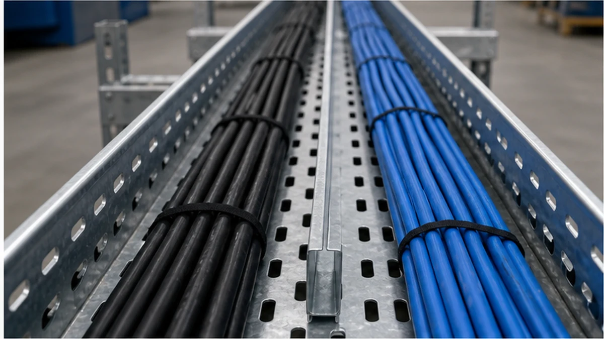
A longitudinal cable tray divider creates defined lanes inside a shared tray run, making intended cable routes visible, repeatable, and inspectable. It is relevant where a single coordinated route must carry power, control, instrumentation, or communications cables and the design calls for physical separation between those groups. The divider is not a universal EMC solution and does not replace applicable electrical installation rules, cable-manufacturer instructions, or the project’s segregation schedule. Its core value is discipline: it encodes the design intent into the installed hardware so that every crew and inspector working on the route can see and verify where each cable family belongs.
This article is written for engineers, contractors, and buyers who need to specify divider-equipped tray without relying on unverified rule-of-thumb spacing or generic part numbers. Where the tray type itself has not yet been selected, start with the broader cable tray system range before drilling into divider geometry.
Divider layout in a cable tray
What a Divider Does—and What It Does Not Do
A longitudinal divider is a formed metal or non-metallic barrier fixed along the tray section. It physically separates compartments so that assigned cable groups stay in the intended lane during pulling, maintenance, and future additions. It also makes the installed arrangement inspectable: an auditor can see at a glance whether the cable groups are positioned as the design requires.
What the divider does not do is equally important. The required segregation distance is a system-design decision governed by cable construction, voltage and current levels, switching noise characteristics, parallel-run length, shielding and bonding arrangement, the equipment at each end, and the governing project specification. A divider alone does not establish a compliant clearance, provide shielding performance, or correct poor termination or bonding practice. Treat it as one coordinated component within the broader electrical and EMC design rather than as a self-contained compliance measure.
The product-system standard for cable tray is IEC 61537. The design team must also identify the installation, EMC, fire, and client requirements that govern the particular route before a divider layout is released for procurement.
Cable-Lane Decision Table
Before selecting a divider height or spacing, map the cable groups that must share the route. The table below offers a structured starting point; populate it from the project cable schedule rather than from generic assumptions.
Cable Service
Voltage Class
Signal Sensitivity
Shield Status
Separation Rule Source
Permitted Lane
LV power distribution
High
—
Unshielded
Project specification
Lane A
Control wiring
Medium
Medium
To be confirmed
Project specification
Lane B
Instrumentation
Low
High
Shielded
EMC design record
Lane C
Data / communications
Low
High
To be confirmed
EMC design record
Lane C or separate tray
Treat this as a working register, not a finished document. The permitted lane column must be confirmed by the electrical and EMC designer before the layout drawing is issued for construction.
Route-Node Continuity: Elbow, Tee, and Reducer Checklist
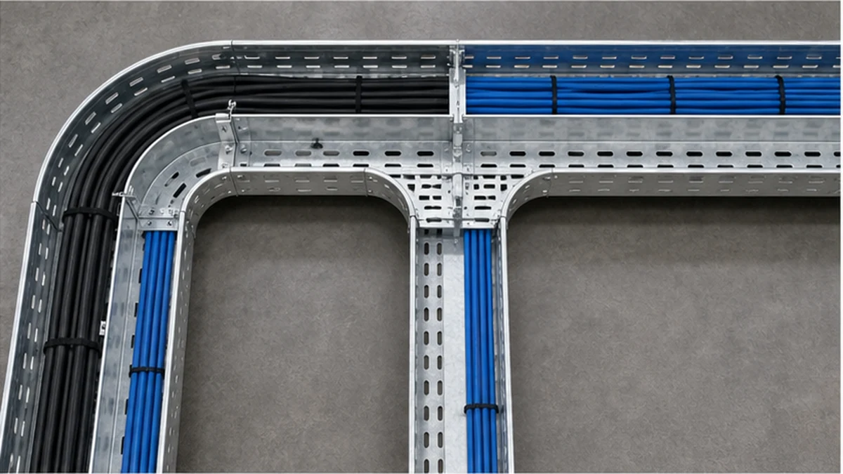
A straight divider that terminates at every fitting is functionally incomplete. The cable groups that the divider separates at mid-run must remain separated through every transition. Before issuing the installation package, verify each route node against the checklist below.
At every horizontal or vertical elbow:
– [ ] Supplier-approved divider elbow detail specified and included in BOM
– [ ] Lane allocation confirmed continuous through the turn
– [ ] Cover clearance checked with divider in position
At every tee junction:
– [ ] Branch lane allocation documented on the route drawing
– [ ] Approved tee transition piece specified for each departing branch
– [ ] Cable groups assigned to correct branch without crossing the divider
At every reducer or expansion joint:
– [ ] Lane width change documented and confirmed against cable fill in both tray widths
– [ ] Approved reducer transition detail specified
– [ ] Splice hardware included in BOM if sections meet at the reducer face
At every riser, drop-out, or equipment entry:
– [ ] Approved detail for how each cable group continues after the divider ends
– [ ] Panel or enclosure entry does not allow cable groups to cross without an approved method
– [ ] Field drilling or cutting (if permitted) documented with corrosion-protection restoration method
Photograph each transition node before cable pulling. Photographs taken at this stage form the most practical evidence that fitting continuity was achieved, because covers and cable bundles will conceal fasteners once the route is complete.
Divider routing through tray fittings
Select a Divider Compatible with the Actual Tray System
Divider geometry is system-specific. Tray width, sidewall profile, base perforation pattern, splice arrangement, cover interface, material, finish, and fitting family all affect whether a divider can be installed continuously through the route. Request a cross-section drawing and a compatible fitting detail from the supplier before accepting any divider item as interchangeable with another tray family.
For a perforated route, confirm whether the divider uses the tray perforation pattern as its fixing datum, a dedicated clip, or a bolted arrangement. The perforated cable tray range provides a starting point for confirming the tray family, but a product page is not a substitute for a project-specific coordinated drawing. On ladder tray, the divider may require dedicated cross-member fixing points. On solid-bottom tray, confirm that the proposed fixing method does not compromise corrosion protection, drainage, or the cable-support surface.
Material and finish must be specified as a matched pair with the tray. Do not assume that a steel divider suits every aluminum, stainless, coated-steel, or FRP installation. The project corrosion strategy should determine whether matching material, a documented isolation method, or another protective detail is required. Where the divider is metallic, the electrical designer must also define whether bonding is needed and how continuity is verified and recorded.
Set compartment widths from the cable schedule. Allow working room for pulling, bend control, tie-down points, future additions, and the permitted fill for each lane. A divider height greater than the cable bundle is not automatically correct: the selected height must still clear covers, fittings, entries, and installation tools. Record final dimensions on the coordinated routing drawing rather than describing them with an unsupported dimension rule.
BOM and Fitting-Transition Matrix
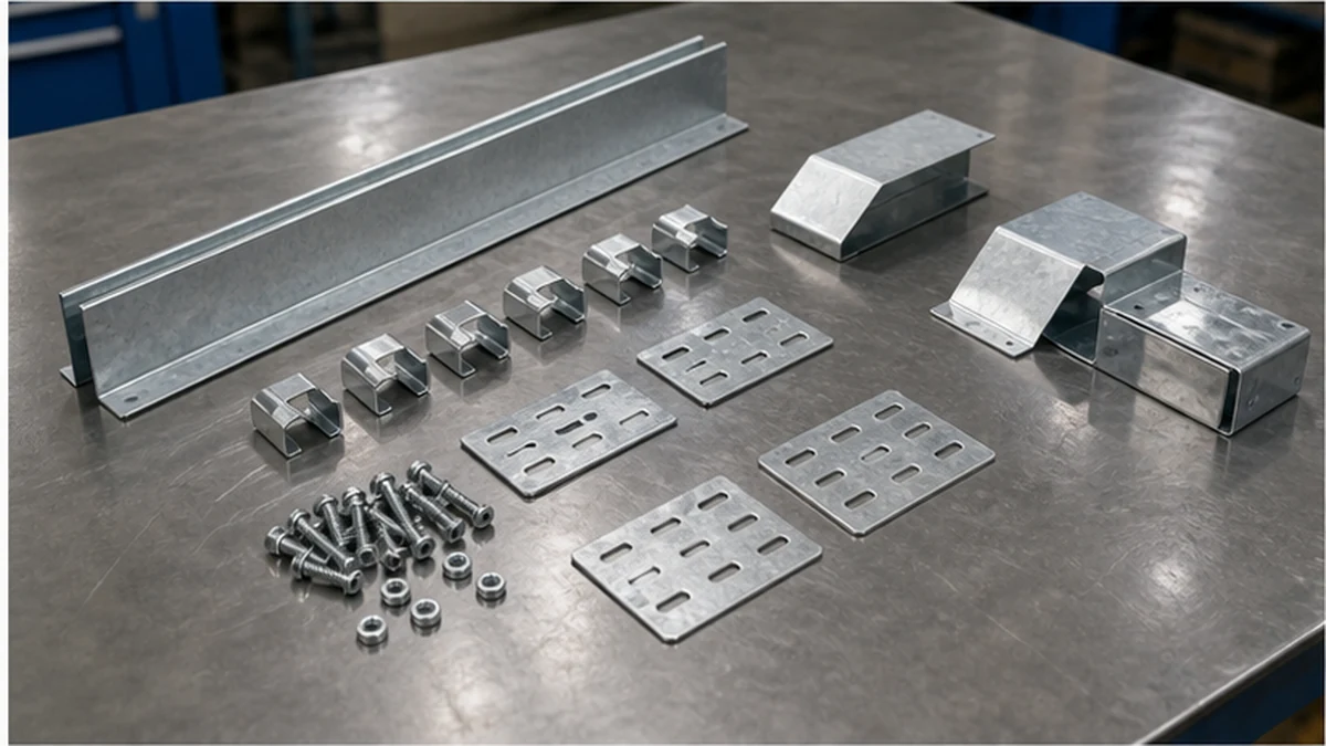
A purchase line that reads only “divider, 3 m” is insufficient for any route that turns, changes width, or carries covers. The bill of materials should reflect the divider as a complete route system. The matrix below maps each route element to the components that must appear in the BOM.
Splice plate or joining piece, fasteners, protective treatment
Horizontal elbow
Approved elbow divider detail or transition piece
Vertical elbow (rise / drop)
Approved riser transition piece
Tee junction
Approved tee divider transition per departing branch
Reducer
Approved reducer transition, splice hardware if sections meet at face
Covered run
Cover-compatible divider element; height checked against cover clearance
Bonded metallic divider
Bonding conductor, clamp, hardware per electrical design
Procurement contingency
Spare or adjustment quantities per project procurement rules
Coordinate this matrix with the cable tray fittings family being used on the same route. Request one route-level takeoff that integrates tray, fittings, and divider hardware. Separately estimating straight tray lengths and divider lengths is one of the most reliable ways to miss transition parts before the order is released.
Divider BOM components
Installation Sequence and Hold Points
Installers should work from the approved layout drawing, not assign lane allocation during cable pulling. A structured sequence reduces the risk of divider gaps and incorrect cable placement:
Install and align the tray run; complete all required mechanical joints.
Fit the divider along the straight run, starting from a confirmed reference point.
Install approved transition pieces at each elbow, tee, reducer, riser, and equipment entry in sequence.
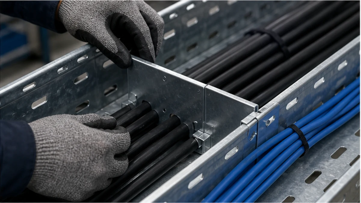
Carry out a pre-pull hold point: confirm the divider is secure, free of sharp edges, and does not obstruct designed access. Record findings.
Pull assigned cable groups into their marked lanes in the confirmed sequence.
Install covers, if used, and verify that they close without pinching cable or deforming the divider.
Photograph the complete route at each fitting transition before cables conceal the fasteners.
Installation hold points that should be formally recorded in the project quality plan:
Hold Point 1 — Tray alignment and joint completion, before divider installation.
Hold Point 2 — Divider and transition fitting installation, before cable pulling.
Hold Point 3 — Cable allocation in lanes, before covers are closed.
Where field drilling or cutting is permitted by the project method statement, document the cutting method and verify that corrosion protection is restored before the route is accepted. The cable tray installation guide provides broader installation context; for divider-equipped routes, add the hold points above to the quality register rather than treating them as implied by the general sequence.
Post-Install Inspection Evidence
The inspection should compare the installed route against the cable schedule and the approved routing drawing at every section, fitting, and entry point. A close-out checklist limited to straight lengths only will miss the most common sources of segregation failure.
Post-installation inspection checklist:
– [ ] Each cable group confirmed in its assigned lane along the full straight run
– [ ] Divider joints secure; no movement under hand load
– [ ] Fitting transitions (elbows, tees, reducers) retain lane assignment; no crossing observed
– [ ] Covers close without pinching cable or compressing divider
– [ ] No cable forced over a divider edge or resting against a cut face
– [ ] Bonding or continuity check results recorded against the electrical design requirement
– [ ] Photographic evidence package assembled for each route node and hold point
– [ ] Cable schedule, route drawing, and any change-control records filed with the asset documentation
Retain the inspection package for future access: additions or maintenance that disturb the divider without a reviewed cable schedule can reintroduce the mixing the divider was installed to prevent. Support planning should also be reviewed against the divider configuration; see the cable tray support planning guidance for the related structural considerations.
Divider installation inspection
Xinma System Coordination
Xinma manufactures cable tray sections together with fittings, covers, accessories, busway components, and seismic-bracing systems that are designed to be specified as a coordinated system. For divider-equipped routes specifically, the procurement check that matters is confirming compatible model codes, matched material and finish, support geometry, and clamp, tap-off, or access interfaces across each element in the selected system. Seismic-bracing components must be confirmed against the divider height and weight contribution where the project seismic design requires it. Busway transitions adjacent to the tray route should be documented in the coordination drawing so that divider termination details and entry methods are resolved before installation begins. Site-inspection consistency is easier to achieve when the BOM references a single system family: the installed part can be checked against the order record without resolving cross-family compatibility questions in the field. Contact the Xinma technical team to confirm compatible assemblies for any route that includes non-standard transitions, mixed tray widths, or covered-to-uncovered changes.
Frequently Asked Questions
Does a divider make power and data cables compliant in the same tray?
No. A divider provides physical lane separation. Whether the arrangement is compliant must still be determined by the applicable design documents, cable requirements, and the project’s electrical or EMC criteria. The divider implements the design intent; it does not establish it.
Can one divider fit every cable tray brand or tray type?
No. Fixing geometry, tray width, base perforation pattern, side-rail profile, fitting family, cover interface, material, and finish can all differ between systems. Confirm compatibility from the supplier’s system drawing and approved fitting detail before accepting a divider as interchangeable.
How high should a cable tray divider be?
Set the height from the approved compartment layout, cable bundle geometry, fitting and cover clearance, and installation access requirements. A fixed height applied without checking those route details is not a reliable design basis.
Should a metallic divider be bonded?
Follow the project’s electrical design record and the local installation requirements. The answer depends on the selected tray system, the defined earthing and bonding arrangement, and the conductor sizes involved. Do not assume bonding is unnecessary without a documented design decision.
What is the most common divider BOM omission?
Missing transition pieces at elbows, tees, reducers, risers, and equipment entries. These omissions are rarely visible in a line-item BOM that lists only straight divider lengths. Review the divider as a complete route system from the coordinated drawing, not as a length of material between the first and last straight section.
Kevin Zheng
Kevin Zheng is a manager linked to Shanghai Xinma Busway & Cable Tray Co., Ltd. He writes technical content on cable tray systems, installation practice, sizing logic, load classes, and related standards for industrial and infrastructure applications.