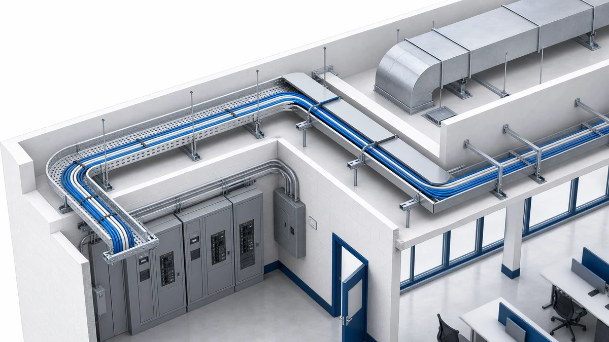
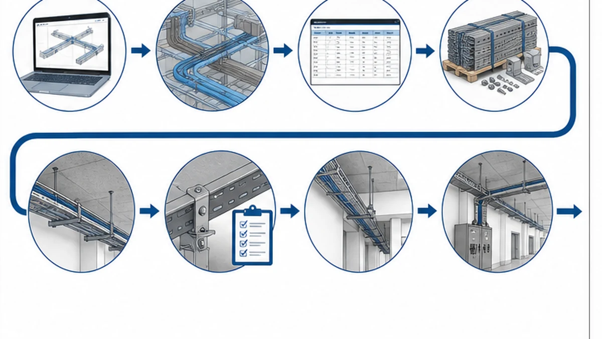
Light-duty cable tray is a project-defined description applied to a route whose selected system, supports, and cable schedule do not require a heavier arrangement. It is not a universal load class, a fixed capacity rating, or a shortcut applicable to every commercial building floor. A single commercial project can contain office floors, electrical rooms, retail spaces, parking areas, service corridors, and plant zones with substantially different cable types, environmental conditions, access requirements, and structural constraints.
Start from the Xinma cable tray system range and the current project documents. The sections below help MEP engineers, EPC procurement teams, and site inspectors evaluate a lighter cable route without treating any fixed width, span, material, fill allowance, or building-use category as a universal rule.
Establish the Decision Framework Before Selecting a System
No single input justifies a light-duty classification. Seven interdependent factors must be reviewed together, and each should be documented before procurement is released.
All seven factors should be resolved before the purchase order is issued. If any factor is still open at that point, note it explicitly as a design hold rather than resolving it informally at installation.
A commercial route must be assessed from actual project inputs.
Define the Route Before Calling It Light-Duty
The design review starts with the current cable schedule and the coordinated route drawing. Identify the cable services, outside dimensions, weights, separation requirements, entry and exit points, maintenance access strategy, ambient environment, approved future scope, and available structure at each support location. These inputs establish whether the selected tray profile and support arrangement are appropriate for that specific route.
Commercial projects frequently include control, communication, security, and building-management routes that warrant a lighter arrangement alongside power or mixed-service routes that require a different system. The room name alone is not a reliable qualifier. A route above a suspended ceiling, inside an electrical room, or adjacent to a plant area must be reviewed against its actual cable schedule, route geometry, support design, and documented project requirements.
Select a Tray Profile From the Route Requirements
The tray profile should serve the cable arrangement, access conditions, environment, and required accessories shown on the approved design. No profile is universally better suited to commercial work.
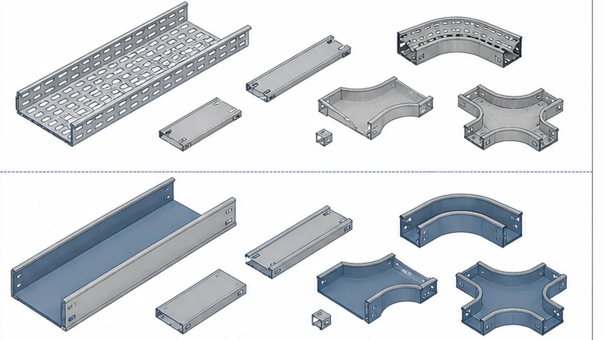
Perforated tray can be considered where the product’s support surface, opening pattern, access characteristics, and fitting family suit the route. Review the perforated cable tray range against the project requirements. The route still needs matched supports, fittings, material, finish, and inspection conditions confirmed by the responsible engineer.
Solid-bottom tray can be considered where the approved design calls for that geometry and any compatible cover or accessory arrangement. The solid cable tray product family is the correct reference for that selection. A continuous base alone does not establish thermal, electrical-continuity, mechanical-protection, or fire performance for the installation; those outcomes depend on the complete approved arrangement.
Other profiles may be appropriate when the cable schedule, support configuration, or route conditions require them. That decision belongs to the responsible engineer and the selected manufacturer’s published data, not a general comparison.
Product selection follows the approved route requirements.
Build a Complete Commercial-Route BOM
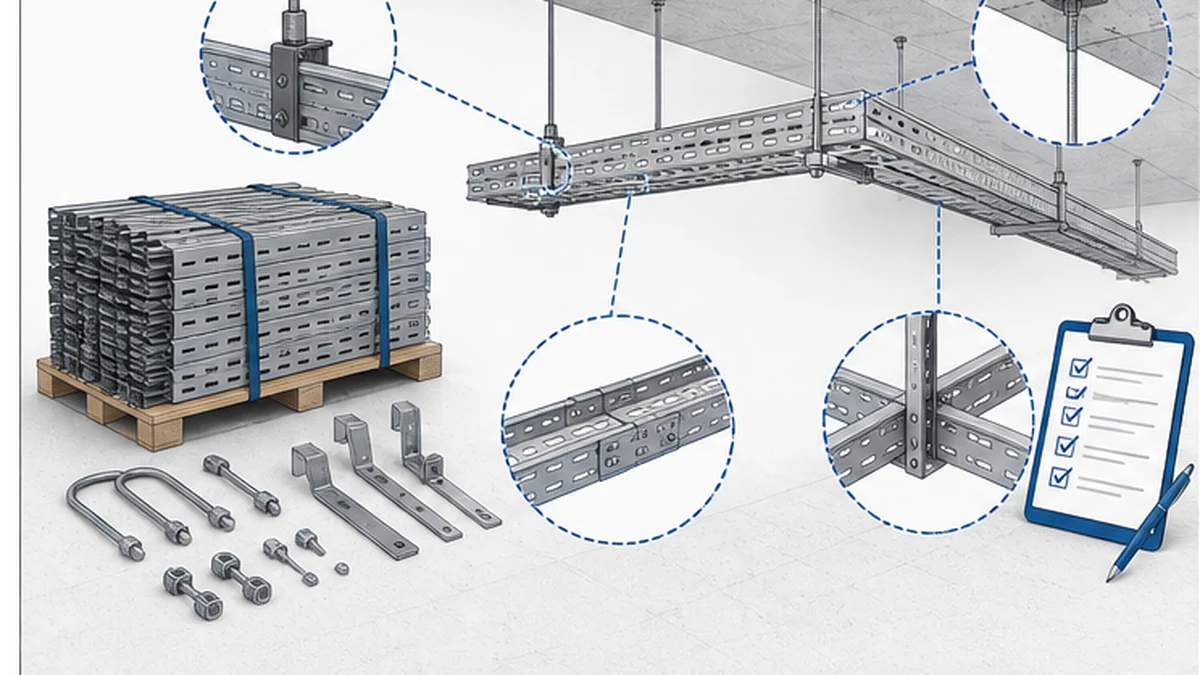
A commercial tray package must cover an installable route, not only straight sections. The table below identifies the minimum scope categories that should appear in the bill of materials before procurement is released.
BOM category
Minimum content required
Straight sections
Type, nominal width and depth, material, finish, quantity per segment
Fittings
Bends, tees, reducers, risers, end caps — each tied to a route segment and drawing reference
Connection hardware
Splice plates, bolts, nuts, washers matched to tray rail profile
Supports
Bracket type, rod or channel size, anchor specification, spacing confirmed against approved design
Covers and dividers
Profile, length, clip family confirmed compatible with adjacent fitting
Accessories
Labels, earth bonding components, cable cleats or clips where specified
Interface items
Fire-stopping support, panel-entry detail, penetration seal scope where the tray contract owns it
At a branch, panel entry, level change, or width transition, the fitting and support arrangement must be explicit in the BOM. A generic “accessories included” statement does not confirm that the needed parts are present or that they are dimensionally compatible with the selected tray family.
Use the cable tray support guide to organize the support review around available structure, support geometry, installation access, and published product data. The responsible engineer confirms the actual anchors, support arrangement, load case, and any seismic or dynamic restraint required by the project.
Material, Finish, and Building Interface Coordination
Selecting material and finish from a broad descriptor such as “indoor commercial” is not a complete material instruction. State the approved corrosion category, finish specification, and any maintenance or service-life condition in the drawings, purchase order, and manufacturer submittal, along with any records the contract requires.
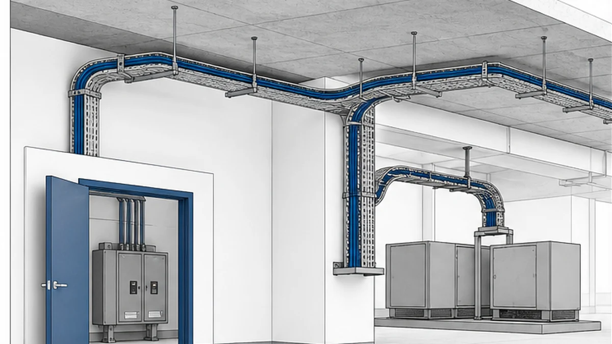
Review building interfaces early. Tray supports can share a structural grid with HVAC, piping, lighting, and other services. Panel entries, equipment drops, fire-stopping scopes, cable-segregation requirements, and maintenance clearances need to appear in the coordinated design before material is committed.
If the project requires a divider, cover, bonding component, seismic restraint, or special edge protection, include the compatible component and the governing document reference in the BOM. Use a pre-delivery trial fit to confirm that sections, clips, and adjacent fitting profiles are compatible before materials are released to the floor.
Receiving checks identify mismatched components before installation.
First-Route Installation Checklist and Inspection Sequence
Before accepting the installed route, work through the following checks in sequence. The first installed route is the most efficient point to confirm that the design, BOM, and site conditions are consistent.
At goods receipt
– Compare delivered part numbers and nominal dimensions against the approved purchase order
– Confirm material or finish identification against the approved submittal
– Check fitting orientation and connection hardware quantities
– Record visible condition, packing damage, and any short-supply items
– Retain delivery documents as required by the project inspection plan
Before cable installation
– Verify that support positions match the approved coordinated drawing revision
– Confirm connection hardware torque or assembly method follows the manufacturer’s instruction
– Check cover clips and divider profiles against the adjacent fitting rail
– Confirm cable-entry and equipment-drop details match the design
– Record any cable-schedule or routing change and trigger a formal review of tray selection, fitting quantities, and remaining materials
Use the cable tray installation guide as a sequence reference alongside the approved method statement. For system-performance context, the IEC 61537 publication is the direct international reference for cable tray systems and cable ladders; final acceptance criteria remain with the project specification, local authority requirements, and the responsible engineer.
Coordinate With Other Commercial Building Services
Commercial cable routes frequently share a ceiling or service corridor with HVAC, plumbing, lighting, controls, and fire-protection systems. Before material is released, confirm that the tray route retains the support positions, equipment clearances, maintenance access, and cable-pulling path shown in the coordinated drawing. A late clash resolution can alter fittings, bracket locations, cover requirements, and the affected cable route substantially enough to invalidate the original BOM.
The purchase package should identify which drawing revision controls the order and which party owns each interface support or penetration detail. When a coordination change occurs after procurement is released, document the impacted tray sections, fittings, supports, and accessories before material is delivered. This gives the procurement and site teams a controlled basis for reconciling the change rather than resolving it informally at installation.
Keep the Commercial Route Traceable Through Handover
At handover, retain the approved drawings, authorized change records, delivery receipts, required material or finish certification, inspection results, and any installation records the project specification requires. This record gives a future maintenance or alteration team a reliable basis for evaluating a new cable, a revised equipment connection, or a route change without having to reconstruct the original design intent from memory or unmarked installations.
Controlled records preserve an installable route.
Xinma Product Ecosystem for Commercial Cable Tray Projects
Xinma supplies cable tray sections, matched fittings, and the accessory families — including covers, dividers, edge protection, and cable clips — needed to build a complete, inspectable commercial route. For commercial buildings with seismic requirements, Xinma’s seismic-bracing components are designed to coordinate with the same tray rail profiles and support geometry, so the engineer can confirm restraint compatibility before the BOM is finalized rather than after installation begins. Busway products within the Xinma range are sized and finished to allow coordinated routing alongside cable tray where the approved design calls for both systems in the same service corridor. Before procurement is released, the project team should verify model codes, nominal dimensions, finish designations, and clamp or splice-plate compatibility across all Xinma product families included in the order. At the first installed route, a site-inspection check should confirm that the delivered fittings, covers, and accessories match the approved submittal and are dimensionally consistent with the adjacent tray sections and supports. Repeat deliveries should be checked against the same submittal revision to avoid finish or profile variation across phases.
Frequently Asked Questions
What does light-duty cable tray mean in a commercial project?
It describes a route where the selected tray system and support arrangement suit the actual approved cable schedule and documented project conditions for that specific route. It should not be applied as a fixed capacity class, a standard span table, or a building-use category that covers an entire project by default.
Is perforated or solid-bottom tray better for commercial buildings?
Neither is universally better. Compare the actual cable route, required access, product geometry, support arrangement, environment, cover or accessory needs, and project requirements before selecting a profile. The responsible engineer determines which product family is appropriate for each route based on those documented inputs.
What should be included in a commercial cable tray BOM?
Include straight sections, matched fittings for each route segment, connection hardware compatible with the selected rail profile, approved supports, specified covers or dividers with compatible clips, labels, bonding components where required, and any interface items the tray contract owns. Every line item should be traceable to the drawing revision or specification clause that requires it.
How should supports be checked for a lighter cable route?
Review the selected system’s published load data alongside the approved support design, the confirmed cable schedule, route geometry, available structure at each support location, specified anchors, and installation access constraints. The responsible engineer approves the final support arrangement, including any seismic or dynamic restraint the project requires.
What should be checked before accepting a commercial cable tray delivery?
Compare delivered part numbers, nominal dimensions, material or finish identification, fitting types and orientations, connection hardware quantities, visible physical condition, and packing information against the approved purchase order and approved submittal. Record findings against the project inspection plan’s sampling and acceptance criteria rather than substituting a generic site rule.
Kevin Zheng
Kevin Zheng is a manager linked to Shanghai Xinma Busway & Cable Tray Co., Ltd. He writes technical content on cable tray systems, installation practice, sizing logic, load classes, and related standards for industrial and infrastructure applications.