Trough cable tray is a formed section with a more continuous cable-bearing surface than an open ladder system. It can be appropriate where a route needs a defined channel for smaller or mixed cables while still allowing practical access from above. The term is applied inconsistently across markets and manufacturers, so the specific section profile, fittings, covers, support arrangement, and finish must always be identified in the approved project documents before procurement or installation begins.
For an initial comparison across the Xinma product range, see the Xinma cable tray overview. This article helps EPC engineers, MEP contractors, procurement teams, and site inspectors decide when a trough-style route deserves consideration. It does not determine the final load rating, cable segregation, environmental classification, grounding arrangement, or fire-performance requirements for any project.
What a Trough Cable Tray Is
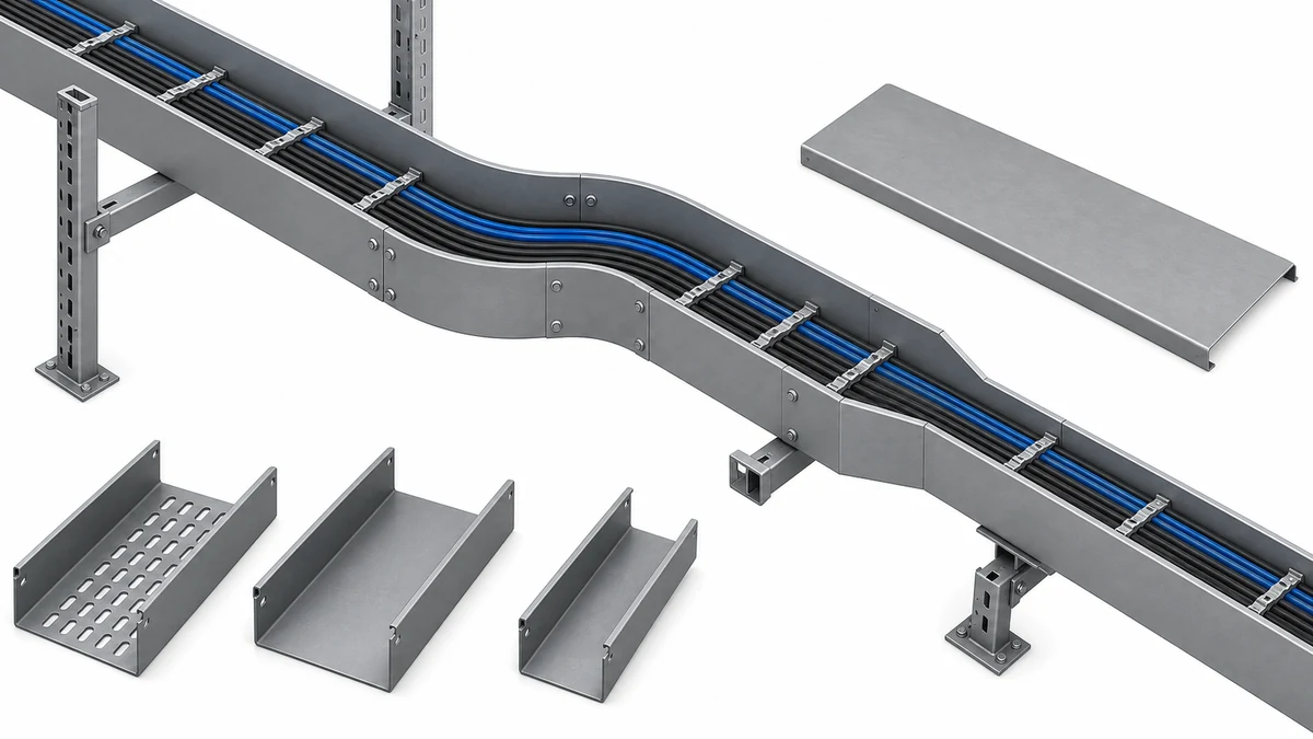
A trough cable tray normally has an open top, formed side rails, and a bottom that provides more bearing surface than ladder rungs. The bottom may be continuous or include a pattern of openings depending on the selected product family. A trough label alone does not communicate usable width, rail geometry, finish, drainage behavior, cover compatibility, or load capacity. Those values come from the selected manufacturer’s data sheets and the approved construction drawings.
The defining characteristic is the cable-support surface. Routes carrying smaller control, instrumentation, communication, or mixed cables may benefit from a more continuous base where the approved design calls for it. Even so, the system must be specified as a complete route, inclusive of matched fittings, splice hardware, supports, covers, and accessories. Selecting a generic U-shaped section and assuming the remaining components will be compatible is not a reliable procurement approach.
A trough route must be specified as a complete system.
Selection Matrix: Trough, Perforated, and Solid-Bottom Systems
The table below maps common route-level inputs to the three enclosed-bottom system types. It is a structured starting point, not a substitution for the approved project design. Every column assumes the project team has confirmed material, finish, covers, fittings, and support geometry against the actual cable schedule and route environment.
Route Condition
Trough
Perforated
Solid-Bottom
Small and mixed cable sizes requiring continuous bearing
Often suitable
Suitable where opening pattern accepts cable diameter
Suitable
Ventilation or heat-dissipation priority
Less favorable without cover openings
Favorable
Less favorable
Liquid drainage required
Check product-specific drainage provisions
Generally favorable
Not suitable without deliberate drain points
Full cable containment or restricted access
Add specified cover
Add specified cover
Inherently more enclosed; add specified cover
Visual cable inspection without cover removal
Possible with open top
Possible with open top
Requires cover removal or access panel
High cable-fill density
Confirm rail depth and load data
Confirm rail depth and load data
Confirm rail depth and load data
EMI segregation or shielding requirement
Not inherent; add dividers or separate tray
Not inherent
Not inherent; check cover and grounding
Corrosive or washdown environment
Select finish per project corrosion strategy
Select finish per project corrosion strategy
Select finish per project corrosion strategy
For the perforated product family, refer to the perforated cable tray range for section geometries, opening patterns, and available accessories. For solid-bottom configurations, the solid cable tray range provides the matched product-family reference. Neither page replaces the project corrosion strategy, structural review, or cable-fill calculation.
Compare route requirements before selecting a tray profile.
Where Trough Support Can Be Appropriate
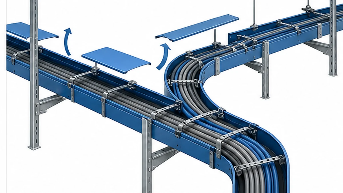
Consider trough cable tray when the route needs a defined channel and a more continuous bottom surface, but the installation still needs accessible cable placement and visual inspection from above. Relevant decision inputs include cable size and type, route environment, maintenance access constraints, required cable separation, expected future modifications, and the approved support design.
An instrumentation route may require an organized channel and clearly controlled branch points. A service area may need more bottom support than an open ladder provides. A short transition from a main power route may require a tray type that accommodates the selected cable bending radius and fitting geometry. No single input from this list proves that trough tray is correct; all inputs must be evaluated together against the project documents.
Specifying the Complete Route, Not Just the Section
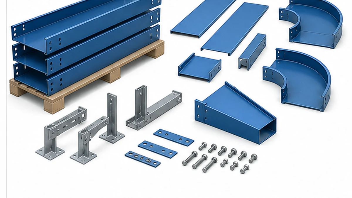
A trough cable tray order should cover every component along the route: straight sections, horizontal and vertical bends, tees, reducers, splice plates, hold-down clips, covers, dividers, end treatments, and supports where specified. At each route change, the project team should confirm fitting orientation, cable arrangement, support position, and the transition to any adjacent tray system. A fitting that appears geometrically similar may not match the selected rail profile, nominal width, rail depth, finish, or cover interface.
The support design is an integral part of the selection, not a downstream task. Use the cable tray support resource to organize a review around available structure, support geometry, installation access, and the selected system’s published load data. The responsible engineer approves the actual support spacing, anchor type, load case, and any seismic or restraint arrangement for the project. Do not transfer a generic support spacing from another tray family or a previous project.
At electrical or structural interfaces, document which discipline owns each component. Where a route requires bonding continuity, a particular cover, special restraint, or protective treatment, state the governing project requirement and include the corresponding parts explicitly in the bill of materials. Do not add an arbitrary material allowance or assume that an ordinary splice plate will satisfy every grounding or structural requirement.
Material, Finish, and Corrosion Selection
Select material and finish against the project’s documented corrosion strategy, maintenance plan, route environment classification, and approved system data. Terms such as “outdoor,” “washdown area,” or “chemical zone” describe conditions; they do not constitute a complete material specification. The final selection belongs in the approved drawings, purchase order, and manufacturer submittal package.
Where a route passes through more than one environment classification, identify the transition point and confirm which finish governs each segment. A finish change at a transition fitting may require a specific compatible splice plate or a different connection method. Include those details in the procurement package and confirm them during design-review sign-off.
Receiving and Installation Workflow
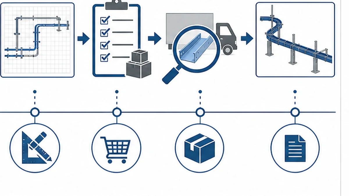
The following sequence organizes the key activities from order release to handover records. The project’s controlled method statement and inspection plan take precedence over any generic workflow.
Pre-order release
– Confirm the route drawing revision that governs the order
– Reconcile every line item: straight sections, bends, reducers, covers, clips, supports, splice hardware, and accessories
– Verify that material and finish descriptions reference the documented environment classification, not a generic label
– Identify hold points, delivery sequence, and required inspection documents
Receipt inspection
– Compare delivered part numbers, nominal dimensions, and material or finish identification with the controlled BOM
– Check fitting orientation, splice-hole alignment, cover profile compatibility, and hardware quantities
– Record visible condition, packing information, and required lot documentation
– Retain records with the delivery before materials are distributed across site
Installation and pre-handover checks
– Install in accordance with approved drawings, manufacturer instructions, and the project method statement
– Before cable pulling, verify the complete route, all fittings, support connections, cover or divider installation where specified, and any required witness-point inspections
– Record authorized route changes, material substitutions, and inspection results
– Confirm that the handover file reflects the installed condition, not the original design intent
For a detailed installation sequence reference, see the cable tray installation guide. For system-performance context under the applicable international standard, refer directly to the IEC 61537 publication. Acceptance depends on the contract documents, local authority requirements, and the selected system’s published data.
Delivery inspection confirms system compatibility.
Route Review Checklist
Use the following checklist before releasing the trough route for cable installation. All items should be verifiable against project documents, not recalled from memory.
[ ] Route drawing revision confirmed and distributed to installation team
[ ] All tray sections, fittings, and accessories reconciled with the approved BOM
[ ] Support positions verified against the approved structural layout and load data
[ ] Covers, clips, and dividers included where the design requires them
[ ] Transition fittings checked for profile, width, depth, and finish compatibility with adjacent system
[ ] Grounding or bonding continuity requirements identified and parts included
[ ] Material and finish confirmed against the documented environment classification for each route segment
[ ] Any seismic-restraint or special-anchorage requirements noted and parts included
[ ] Delivery inspection records retained and linked to the purchase order
[ ] Authorized deviations or substitutions recorded in the as-built file
[ ] Required hold points or witness inspections scheduled before cable-pulling commences
Controlled installation records support handover.
Xinma Ecosystem Considerations
Xinma manufactures trough cable tray sections together with the fittings, covers, hold-down clips, dividers, support brackets, and splice hardware that form a matched route package. Where a project also involves busway distribution, Xinma seismic-bracing components are available and should be reviewed for interface compatibility with the selected tray rail profile, support geometry, and anchor pattern before the structural engineer finalizes the restraint design. For mixed routes that include both trough and perforated or solid-bottom segments, confirm that the splice plate, cover profile, and clip series are consistent at each transition rather than assuming cross-series compatibility. Site-inspection checks should verify that the delivered finish, fitting orientation, and cover-to-rail fit match the controlled BOM at each phase of the installation, and that seismic-restraint positions align with the approved structural attachment points. The project team retains responsibility for all engineering decisions, acceptance criteria, and handover records.
Frequently Asked Questions
What is the difference between trough cable tray and solid-bottom tray?
Both can provide a more continuous bearing surface than ladder tray, but the bottom geometry, drainage provision, cover compatibility, and available accessories can differ between product families. Compare the required cable support, access arrangement, drainage behavior, cover and fitting options, and the manufacturer’s published data for the specific route before selecting either type.
When should trough cable tray be considered instead of ladder tray?
Consider it when the approved route requires a defined channel and more continuous cable support, particularly for smaller control, instrumentation, or mixed cables. Evaluate the cable schedule, maintenance access requirements, support design, compatible fittings, and the documented environment before committing to either system.
Can trough tray accommodate covers and dividers?
It can when the selected product family provides compatible covers, clips, and dividers and the project design requires them. All cover pieces, clips, and associated hardware should be identified explicitly in the BOM rather than added as field decisions during installation.
How should trough cable tray support spacing be determined?
The responsible engineer should derive support spacing from the selected tray’s published load data, the calculated cable load, the route geometry, available structural attachment points, and the project’s anchor requirements. Do not apply a generic spacing value taken from a different tray family or from a previous project with different conditions.
What should be inspected when trough cable tray arrives on site?
Check part numbers, nominal dimensions, material or finish identification, fitting and cover profile compatibility, hardware quantities, visible condition, and packing information against the approved purchase order and inspection plan. Retain all required lot records with the delivery before materials are distributed across the site.
Kevin Zheng
Kevin Zheng is a manager linked to Shanghai Xinma Busway & Cable Tray Co., Ltd. He writes technical content on cable tray systems, installation practice, sizing logic, load classes, and related standards for industrial and infrastructure applications.