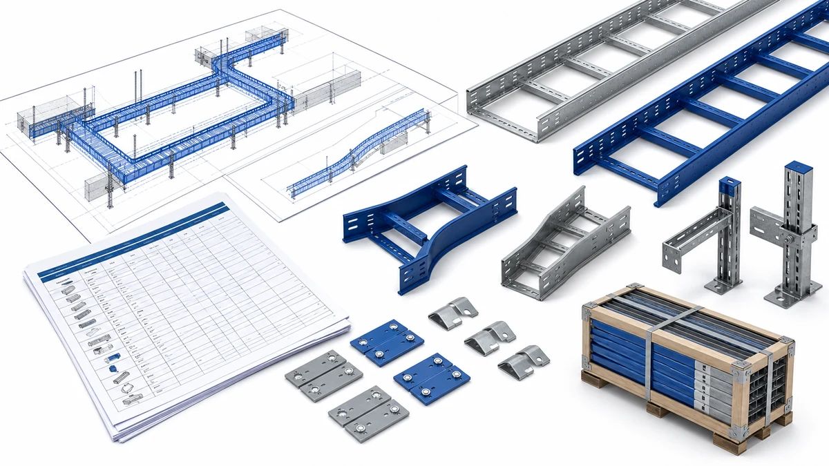
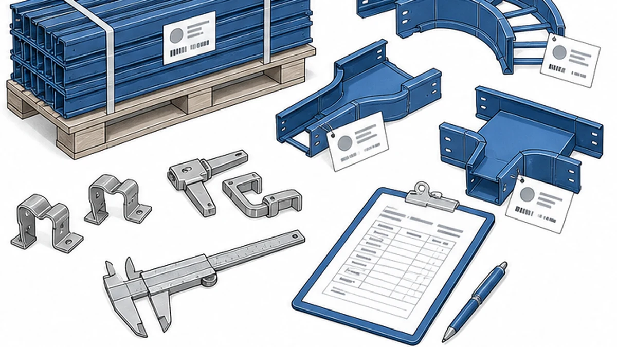
A cable tray bill of materials should describe an installable route, not just a quantity of straight sections. For an EPC or MEP purchase order, it connects approved drawings, the cable schedule, tray sections, fittings, supports, accessories, inspection requirements, and delivery sequence. A low unit price does not show whether the package can complete the route.
Begin the review with the Xinma cable tray system range, then compare the selected product family against current project documents. The buyer’s role is not to substitute for the responsible engineer’s load, grounding, or restraint design. It is to make scope, interfaces, and inspection evidence visible before material is released to order.
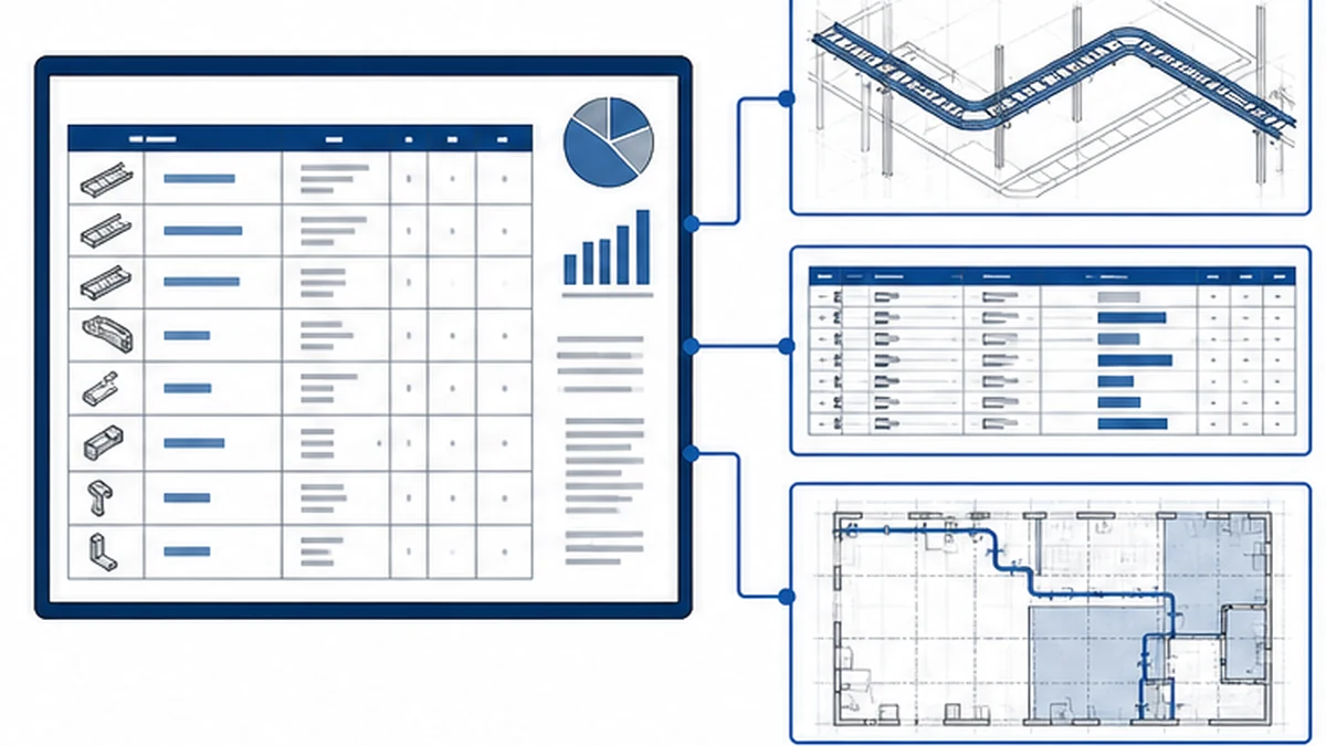
Build the BOM From a Controlled Route and Cable Schedule
Use the latest approved route drawing or coordinated model extract as the authoritative BOM source. Each run should be traceable to a location, tray type, nominal width, side-rail depth, material, finish, and cable service. The cable schedule gives the design team the cable diameter, weight per metre, separation requirement, and any project-defined fill allowance used to select the tray. Do not infer those fields from a visually similar installation.
Separate the route into environmental and operating zones before taking off quantities. Dry electrical rooms, outdoor racks, washdown areas, and chemical-process zones can require different materials, covers, access provisions, and hardware. A generic description such as “industrial hot-dip galvanized tray” does not resolve those distinctions.
Controlled design inputs establish the tray BOM.
The quantity take-off must also identify every direction change, level transition, and width change. A straight-run count does not expose the required elbows, tees, crosses, reducers, risers, cover pieces, or support transitions. If a route segment remains subject to coordination changes, record the drawing revision status and hold the affected quantities until the document is controlled and issued for construction.
Route-level BOM data reduces ambiguity during quotation review and helps receiving staff match delivered lots to specific segments. Add project-specific columns for lot identity, delivery sequence, or classification requirements.
BOM Field
Content Required
Notes
Route ID
Drawing reference and revision
Locked to an approved issue
Zone / Environment
Dry indoor / outdoor / washdown / hazardous
Drives material and finish selection
Tray type
Ladder / perforated / solid-bottom / wire
Per manufacturer product code
Nominal width × depth
mm × mm
Match to approved manufacturer data
Material and finish
Carbon steel HDG / stainless / GRP etc.
Confirm to drawing note
Section length
mm
Match catalogue unit length
Quantity (sections)
Integer
From take-off, by segment
Fittings list
Bend / tee / cross / reducer / riser per change point
Each as a separate line
Support type
Trapeze / wall bracket / cantilever / rod
Per approved support design
Accessories
Cover / divider / clip / bonding jumper
Only where drawing specifies
Connection hardware
Splice plates / bolts / nuts / washers
Confirm inclusion or exclusion
Delivery group
Segment or lot code
For phased construction
Use the matrix before comparing quotations. It makes omitted reducing fittings, cover-retention parts, or connection hardware visible as scope gaps rather than site allowances.
Match Tray Sections and Fittings as Paired Line Items
For every tray section, state the product type, nominal dimensions, material, finish, section length, and connection method. These fields must agree with the approved manufacturer data and drawing note, not a generic catalogue description. Apply the same control to covers and dividers.
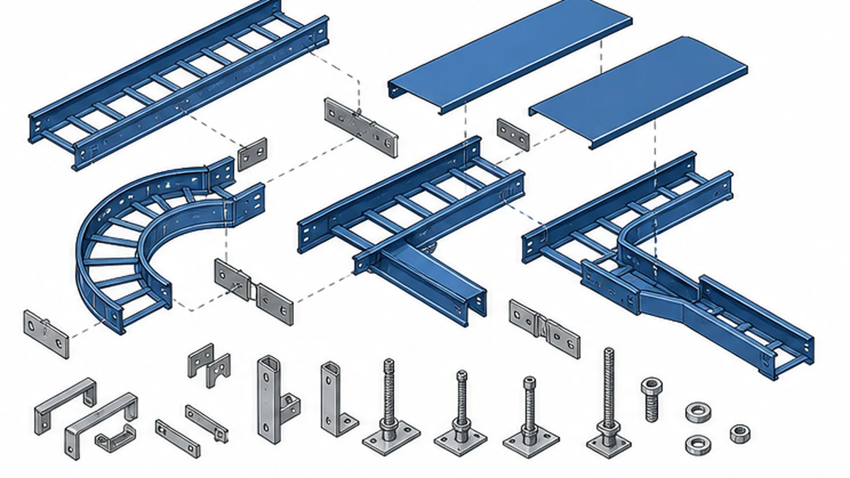
Fittings are separate, measurable BOM lines. The cable tray fittings range provides the compatibility reference for horizontal and vertical bends, tees, crosses, reducers, risers, and splice hardware. Check each fitting against the adjacent tray family, width, depth, rail profile, material, and finish. A nominally similar part from a different product line can produce a dimensional mismatch at the splice or cover interface that requires a field modification.
An installable tray BOM includes matched components.
Confirm that straight sections, joint hardware, mapped fittings, specified accessories, approved support components, and required delivery records all appear as explicit quotation lines.
Drawing-to-Quotation Reconciliation Workflow
Before issuing a purchase order, the following sequence reduces the risk of scope gaps reaching site:
Freeze the drawing revision. Confirm the route drawing is approved for construction and note the revision on the BOM header.
Extract the take-off. Count straight sections, map every fitting location, list supports by type, and note accessories from the drawing annotation.
Populate the route-level matrix. Use the column structure above to assign part codes, quantities, and delivery groups.
Obtain the supplier quotation. Request that the quotation uses the same line-item structure as the BOM matrix.
Line-by-line comparison. Mark each matrix row as covered, missing, or substituted in the quotation. Flag substitutions for engineer review.
Resolve gaps before release. Return missing items to the supplier or add supplementary order lines. Do not treat a gap as a site allowance.
Record the reconciled BOM. Attach the final matrix to the purchase order as a controlled document and update it if the drawing is revised before delivery.
Verify Supports and Structural Interfaces
Tray selection and support design are interdependent. The responsible engineer confirms the manufacturer’s published load data, the approved support spacing, cable weight distribution, route geometry, anchor arrangement, and structural capacity for the specific project. Procurement confirms those approved choices appear in the supply scope. A tray width alone does not determine which brackets, rods, anchors, or clamps the route requires.
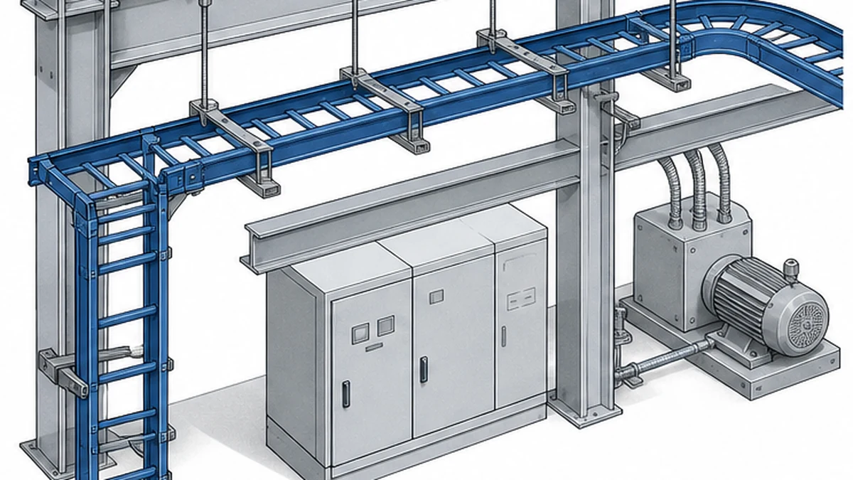
The cable tray support guide is a practical cross-check for available structure, support configuration, installation access, and the selected tray system. At busway interfaces, congested corridors, or vertical drops, identify the trade responsible for each support and confirm cable-pulling and maintenance clearances.
Support scope and system interfaces need review before release.
Where the project requires seismic restraint, grounding continuity, fire-rated enclosure, or hazardous-area controls, the governing requirement and its design reference must appear in the purchase package. Do not apply a generic percentage allowance for these items, and do not assume that standard splice hardware satisfies a project-specific electrical continuity or structural restraint requirement. The responsible engineer and the approved manufacturer documentation determine the final components.
Fitting and Accessory Decision Rules
Accessories are often low unit-value items, but missing or incompatible accessories can halt installation. The cable tray accessories page helps the buyer verify the available product family against the project BOM. The table below summarises common decision points:
Condition on Drawing
Item to Confirm in BOM
Common Omission Risk
Covered route
Compatible covers and retention clips
Clips ordered for wrong tray width
Segregated cables
Dividers and their connection hardware
Divider geometry mismatched to fitting
Vertical drop or riser
Cable restraint clamps shown on drawing
Clamps assumed installer-supplied
Corrosive or washdown zone
Matching finish on every accessory
Accessories supplied in standard finish only
Electrical continuity required
Bonding jumpers, lugs, test points
Items absent from quotation line items
Hazardous area
Product certification documents
Certificates not requested at order stage
Phased delivery
Lot codes aligned to route segments
Mixed lots creating site tracking difficulty
Confirm which accessories are supplied with the main tray sections and which require a separate order. State any installer-supplied consumables explicitly rather than leaving them absent from the order without comment.
Receiving Inspection Checklist
Goods receipt should compare the delivered package with the approved purchase order, drawings, and packing information. The project inspection plan sets the sample method and acceptance criteria.
Quantity and identity
– [ ] Delivered quantities match the purchase order and packing list for each line item
– [ ] Part numbers or product codes correspond to the approved BOM
– [ ] Lot labels or batch numbers are present and legible
Physical condition
– [ ] Representative sections inspected for dimensional conformance (width, depth, length)
– [ ] Splice-hole pattern and pitch align between adjacent sections and fittings
– [ ] Rail profiles and cover-seat geometry match across straight sections, bends, and reducers
– [ ] No visible burrs, sharp edges, or deformation at cut ends or punched holes
– [ ] Coating, finish, or galvanizing layer shows no visible bare areas beyond the manufacturer’s permitted limits
Documentation
– [ ] Mill certificates, material declarations, or test records requested by the contract are present
– [ ] Any hazardous-area or seismic-classification documents are included where specified
– [ ] Packing list, delivery docket, and lot identification are retained for the project record
Record discrepancies while material remains controlled at the delivery area. Retain permitted photographs, required dimensional records, and the certificates requested by the specification.
For the installation-stage check, use the cable tray installation guide alongside the project method statement. The IEC 61537 standard is a direct reference for system-performance context: IEC 61537. Neither source replaces the project specification, applicable local regulations, or the manufacturer’s published data for the selected system.
Delivery inspection compares the package with the approved BOM.
Change Control: Keeping the BOM Current Through Construction
The BOM is a live document. Routing changes, substitutions, or phased delivery revisions that are not formally recorded create a gap between the purchase record and the installed condition.
When a construction change affects a fitting, support type, cable separation arrangement, material, or remaining quantities, apply the following controls before treating the change as an as-built condition:
Confirm the revised drawing or instruction is approved and carries a new revision identifier
Update the route-level BOM matrix to reflect the changed items and quantities
Record the reason for the substitution and the approving authority
Adjust delivery lots or supplementary orders to match the revised scope
Attach the updated matrix to the handover package so that the as-built record reflects actual installed components
Mark up authorised routing changes, reconcile delivery lots, and retain all inspection results with the handover package. Traceability from the approved BOM to documented installed routes supports future maintenance, modification planning, and regulatory audits.
The Xinma Supply Coordination Perspective
Xinma manufactures cable tray sections together with a matched range of fittings, accessories, busway components, and seismic-bracing hardware. For projects that require coordinated supply, this means it is practical to review product codes, material grades, finish standards, support geometry, clamp compatibility, and BOM revisions across related items within a single product family. When site-inspection checks identify a dimensional or finish discrepancy during receiving, cross-referencing the accessory or fitting against the same manufacturer’s data reduces the effort needed to identify the correct replacement or supplementary component. Compatibility between the tray rail profile, the fitting splice geometry, and the seismic-brace attachment point is easier to verify when the components share a common design basis. Final engineering acceptance, load confirmation, and electrical or structural compliance determination remain with the responsible project team.
Frequently Asked Questions
What should a cable tray bill of materials include?
It should identify the selected tray sections, matched fittings, connection hardware, covers or dividers where the specification requires them, supports, required accessories, and the documents needed for delivery inspection. Every line should be traceable to an approved drawing, specification, or manufacturer data reference. A BOM that lists only straight sections and a total length is not sufficient for procurement or receiving purposes.
Are cable tray fittings normally included with straight sections?
Do not assume so. Elbows, tees, reducers, risers, splice plates, clips, and fasteners should appear as individual BOM lines or as explicitly included package items confirmed in the quotation. Compare the supplier’s quotation line by line with the route drawing before issuing the purchase order. Absent fittings are one of the most common causes of field delays on cable tray installations.
How should a buyer check support items in a cable tray BOM?
Compare the support scope with the approved support design, the structural information available for the route, the selected tray manufacturer’s load data, and the planned installation sequence. Confirm who supplies brackets, rods, anchors, clamps, and connection hardware for each route segment, and ensure those items appear in the purchase order rather than being left as a site assumption.
What should be checked when cable tray materials arrive on site?
Match delivered quantities and part numbers to the approved BOM, then inspect representative sections and fittings for dimensional conformance, finish or material identification, connection-hole alignment, visible damage, and any certificates required by the contract. Use the project inspection plan to determine the sample size and acceptance criteria. Record discrepancies before material leaves the controlled delivery area.
Can tray sections and fittings from different suppliers be combined?
Only after the project team has confirmed compatibility for nominal dimensions, rail profile, hole pitch and pattern, material grade, finish, and any electrical continuity requirement. A matched system from a single product family reduces the likelihood of field modification at splice and cover interfaces, but the final compatibility determination belongs to the responsible engineer, not to the procurement record alone.
Kevin Zheng
Kevin Zheng is a manager linked to Shanghai Xinma Busway & Cable Tray Co., Ltd. He writes technical content on cable tray systems, installation practice, sizing logic, load classes, and related standards for industrial and infrastructure applications.