Address
304 North Cardinal St.
Dorchester Center, MA 02124
Work Hours
Monday to Friday: 7AM - 7PM
Weekend: 10AM - 5PM
Address
304 North Cardinal St.
Dorchester Center, MA 02124
Work Hours
Monday to Friday: 7AM - 7PM
Weekend: 10AM - 5PM
Get premium quality cable management systems directly from the manufacturer.
Fill out the form below to receive our catalog and pricing.
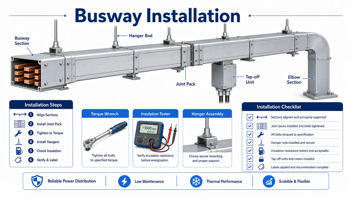
Busway installation quality is decided at the joints. A route can have the correct current rating, conductor material, enclosure rating, and support layout, but still fail inspection if section alignment, joint-pack cleanliness, torque sequence, insulation resistance, or enclosure continuity is not controlled. A practical installation workflow should move from delivery check to dry-fit alignment, joint assembly, torque verification, insulation testing, support inspection, and energization approval.
For the product side of the workflow, Xinma’s busway systems should be reviewed as a complete route package: straight sections, elbows, joint packs, hangers, tap-off boxes, labels, and installation instructions. Installation should never be treated as simply connecting metal ducts end to end.
Before lifting any section, match the delivered materials against the approved bill of materials. Check section labels, rated current, conductor material, IP rating, joint packs, end feeds, elbows, tap-off boxes, hangers, and accessories. If labels do not match the route drawing, stop before installation. A wrong section installed in the middle of a run can create phase sequence errors, missing tap-off positions, or joint mismatch that is hard to correct after lifting.
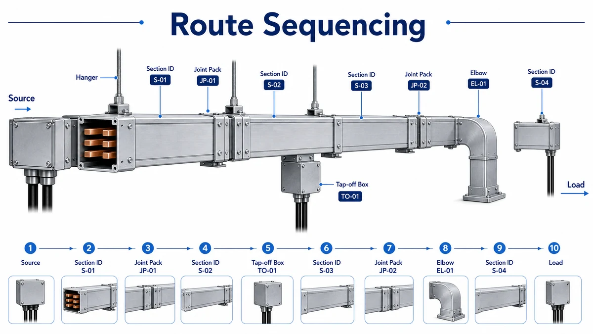
The route sequence should be laid out on the floor or checked against the packing list before installation. Feeder busway routes normally follow a fixed source-to-load order. Plug-in busway routes require extra attention because tap-off windows must face the intended access side and match the planned branch locations.
In an anonymized Shanghai commercial riser installation in 2024, the site team found two swapped 2 m sections during pre-lift inspection. Correcting the order before lifting avoided a tap-off access conflict on the fourth floor and saved roughly one day of rework. The lesson was simple: section sequencing is an installation control, not only a warehouse task.
Busway sections should be aligned mechanically before torque is applied. The joint pack is not a tool for pulling misaligned sections into place. If installers use joint bolts to force alignment, the conductor contact face, insulation barrier, or enclosure gasket may be stressed before the route is energized.
Check horizontal level, vertical offset, support height, enclosure gap, and phase orientation before inserting the joint pack. The joint should slide into position without forcing. If the section faces do not line up, correct the hanger, bracket, or support position first. This is especially important at elbows, risers, transformer connections, and switchboard entries where the route has limited adjustment tolerance.
The installation team should also keep joint contact surfaces clean. Dust, metal chips, moisture, or packaging residue can reduce contact quality. If the manufacturer’s instruction requires cleaning or visual inspection before assembly, record that step in the site checklist.
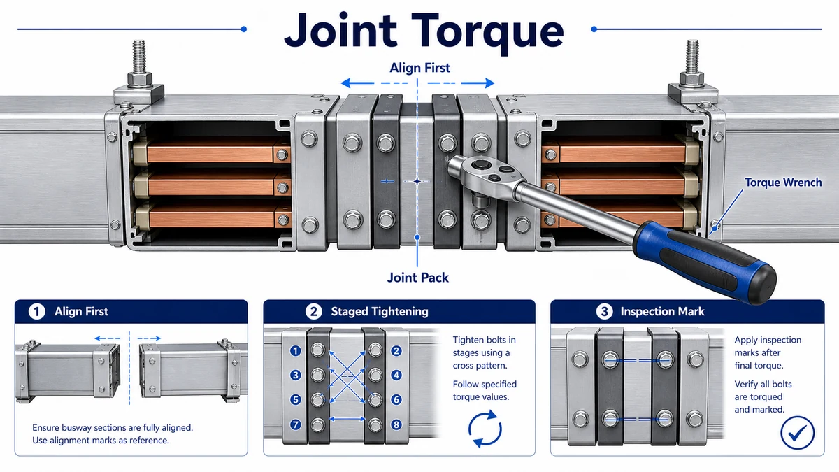
Torque verification is one of the most important installation records for busway. Under-torque can create high contact resistance and local heating. Over-torque can damage threads, compress insulation incorrectly, or deform joint hardware. Use the manufacturer’s stated torque value and tool method for the actual joint pack, not a generic value copied from another busway system.
The torque wrench should be calibrated and suitable for the required range. Apply torque in the recommended sequence, usually in stages rather than one hard tightening pass. If the joint design uses shear-head bolts, Belleville washers, torque indicators, or inspection marks, follow the manufacturer’s documentation and keep photographic evidence where required by the project QA plan.
IEC 61439-6 covers low-voltage busbar trunking systems, including verification context for busbar trunking assemblies. The official IEC 61439-6 publication page is the authority reference to cite when reviewing busway documentation and type-test evidence. Site torque values still come from the manufacturer, because joint design differs by product family.
A good torque record lists route name, joint number, section IDs, installer, date, tool serial number, torque value, and inspector sign-off. For long routes, joint numbers should match the as-built drawing. This avoids vague records such as “all joints checked”, which are hard to defend during troubleshooting.
The record should also show what was not energized during the check. Temporary covers, disconnected tap-off boxes, open inspection windows, and downstream loads removed for testing should be listed so the final energization approval is traceable. If a joint is reopened after the first torque record, treat it as a new inspection point. Reusing the old sign-off after rework weakens the QA file and can hide the exact point where a later heating issue started.
For larger projects, a simple joint register is more useful than scattered photos in a chat group. Number the joints on the route drawing, mark each section label, attach the torque photo to the same joint number, and keep the calibration certificate for the torque wrench in the turnover package. This is not paperwork for its own sake. It gives the maintenance team a clear route map if thermal imaging, odor, noise, or nuisance tripping appears after commissioning.
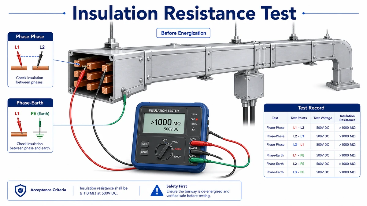
After mechanical assembly, insulation resistance testing verifies that the route has no obvious insulation damage, moisture problem, phase-to-phase fault, or phase-to-earth fault before energization. The test should follow the manufacturer’s installation manual and the project electrical specification.
Typical records include test voltage, test duration, ambient condition, phase-to-phase readings, phase-to-earth readings, and any accessories disconnected during testing. If readings are lower than expected, do not energize the route first and investigate later. Check moisture, damaged insulation, foreign objects, incorrect joint assembly, and connected downstream equipment.
In an anonymized Suzhou factory expansion in 2023, a newly installed 1250 A busway route passed visual inspection but failed the first insulation resistance test after a humid weekend. The team dried the affected joint area, replaced one damaged insulating barrier, and retested before energization. The delay was less costly than energizing a questionable route and chasing a fault later.
Support inspection is not secondary. Busway has concentrated weight at joints, elbows, tap-off boxes, end feeds, and vertical transitions. Hanger spacing, bracket type, anchor selection, vertical riser restraint, and expansion allowance should match the approved drawing and manufacturer’s instructions.
Where busway shares a ceiling zone with cable tray, coordinate bracket positions early. The cable tray support workflow is useful because many of the same field problems apply: supports too far from bends, insufficient clearance around fittings, and access blocked by other trades.
Access clearance must also be checked. Joint covers, tap-off boxes, inspection windows, and labels should remain visible and reachable after all nearby services are installed. If a duct, pipe, tray, or wall blocks a joint cover, the route may pass electrical testing but fail long-term maintainability.
Check the route after neighboring trades finish, not only on the day busway is installed. Fire pipe, air duct, lighting trunking, and cable tray work can change the real clearance around the route. A practical acceptance walk should confirm that covers can still be opened, tap-off boxes can be removed safely, labels are readable from the service side, and there is enough working space for a future shutdown inspection.
Support review should include visible deformation. Hanger rods should be vertical unless the approved detail allows an offset. Brackets should not twist the enclosure. Anchors should not sit too close to slab edges or unapproved inserts. If the route includes a riser, the installer should confirm vertical restraint, floor penetration clearance, firestop coordination, and section weight transfer. These checks reduce the chance that a mechanically acceptable route becomes difficult to inspect or unsafe to maintain.
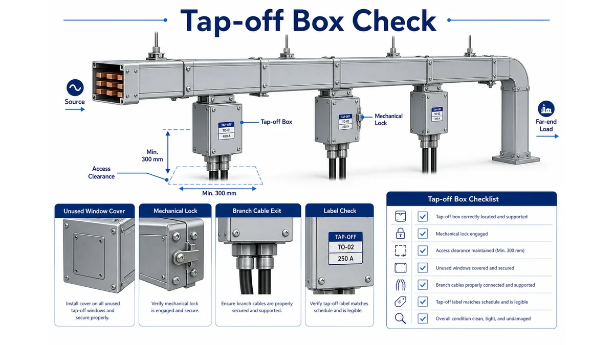
Plug-in busway needs additional checks after the main route is assembled. Tap-off boxes must match the plug-in window format, branch rating, pole configuration, interlock style, and access direction. Do not assume that any tap-off box from the same supplier fits every series or rating.
Before energization, verify tap-off box label, branch protection rating, mechanical lock, door operation, gasket condition, phase orientation, and cable exit direction. Unused plug-in windows should be closed with proper covers or sealing accessories. Branch cables leaving tap-off boxes may still need tray routing, separation, and support; the cable tray systems overview helps keep cable-support assumptions separate from the enclosed busway package.
Shanghai Xinma manufactures busway, cable tray, fittings, accessories, and seismic bracing components within the same product ecosystem. That matters when busway hangers share support steel with tray brackets, when tap-off cable exits must align with cable tray routes, and when a project needs repeated deliveries across several phases. The value is not a marketing ranking; it is the ability to keep model codes, finishes, support geometry, tap-off clearance, and inspection documents consistent from bill of materials to site inspection.
When specifying Xinma products, use the live busway product page as the primary landing page for route and installation review, and cross-check cable routing against the relevant cable tray system and seismic bracing pages before finalizing the order.
For seismic or vibration-sensitive projects, coordinate hanger loads and restraint points with seismic bracing requirements. Busway sections, tap-off boxes, elbows, and risers can create concentrated loads that affect bracket and anchor selection.
Joint quality is usually the most important check. Section alignment, joint-pack cleanliness, correct torque, insulation resistance, and enclosure continuity should be verified before energization.
A normal wrench is not enough for final verification. Use the manufacturer’s required torque method and a calibrated torque wrench, shear-head bolt process, or approved torque indicator method for the specific joint pack.
Test after mechanical assembly and before energization. If the route includes connected downstream equipment, follow the project test method so readings are not distorted by loads or accessories.
Common causes include poor alignment, low contact pressure, incorrect torque, dirty contact surfaces, damaged insulation barriers, moisture, overloaded routes, or mismatched joint hardware.
Record section IDs, joint numbers, torque values, tool calibration, insulation resistance readings, support inspection, tap-off box checks, enclosure continuity, photos, and inspector sign-off.
