How to Choose Cable Tray Systems for Data Centers with Dense Power and Low-Voltage Runs
Base cable tray selection on three constraints: load (kg/m), separation, and access. First, calculate combined power and low-voltage cable mass per meter and match it to an IEC 61537 / NEMA VE 1 load class with ≤3 m support spans. Then enforce physical segregation, EMC needs, and maintenance access along every routed segment.
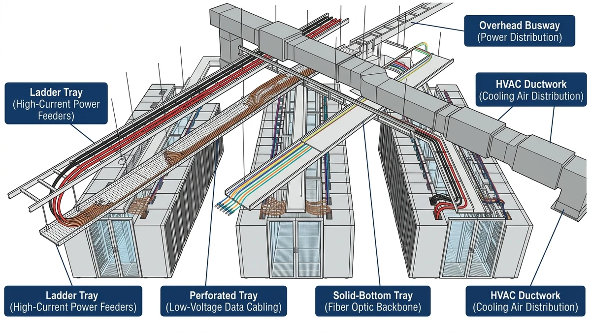
Matching Tray Types to Power and Low-Voltage Circuits
In a data center cable tray system, matching tray types to power and low-voltage circuits comes down to voltage level, fault energy, segregation needs, and cable density. For most layouts, that means one tray strategy for ≥400 V power and another for ELV/IT circuits below 120 V.
In practical terms: decide which circuits can physically share a tray, which must be separated, and which require barriers or covers. From there, you can choose ladder, wire mesh, or solid/perforated bottoms and then size load classes and spans.
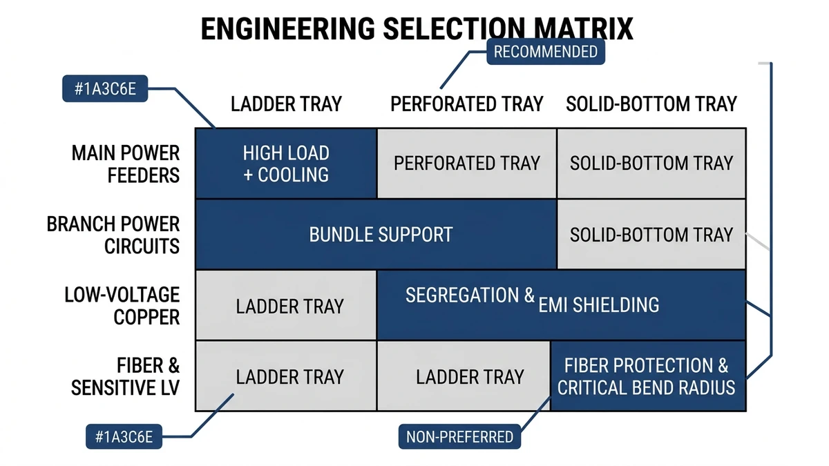
Selection Matrix by Circuit Type
Use this matrix as a starting point; then refine for load class (e.g., 100–200 kg/m), support span (typically 2–3 m), and required segregation.
Circuit type
Typical voltage / use
Recommended tray type
Advantages
Limitations / checks
Main feeder power
400–690 V, ≥400 A
Heavy-duty ladder tray (steel)
High load capacity, good heat dissipation, easy cleats
Needs earthing, check short-circuit restraint and EMC
UPS output / PDU feeds
230/400 V, 100–400 A
Ladder or deep solid-bottom tray
Supports larger bend radius, organized grouping
Control thermal rise; verify support span at 150 kg/m
Branch power to racks
230 V, 16–63 A
Wire mesh tray or light ladder
Flexible routing above racks, easy adds/moves
Limit fill ratio (~40–50 %); protect from debris
DC bus / battery strings
48–380 V DC
Ladder with side rails, sometimes covered
Clear cleating, fault containment, defined routing
Maintain ≥300 mm separation from power when parallel
Row-level copper / patch bundles
Low-voltage, high density
Shallow wire mesh tray
Easy reconfiguration, drop-outs at racks
Watch cable stack height; avoid over-tight ties
Control & monitoring (BMS, fire, PLC)
24 V DC, 230 V AC mixed
Solid-bottom or duct-type tray
Physical and functional segregation possible
Maintain separation between SELV and 230 V groups
Security & access control
12–48 V, often shielded
Wire mesh or solid-bottom, covered in public
Tamper resistance, concealment
Account for added cover mass in support design
How to Apply the Matrix
Define voltage and fault duty
For trays carrying circuits with prospective fault currents above roughly 10 kA, favor rigid ladder tray with certified accessories so cleats and supports can withstand electromechanical forces. NEMA VE 1 provides tray performance and test methods for mechanical loading and support design .
Plan segregation and separation
Run power and data in separate trays or with physical barriers. As a rule of thumb, keep at least 150–300 mm horizontal separation when they share the same support tier; increase for very noisy loads such as UPS inputs or VFDs. When space is tight, specify metallic dividers and verify bonding to the earthing system.
Match tray bottom to cable type
Ladder: best for large power cables ≥50 mm² needing ventilation and easy cleating.
Wire mesh: ideal for dense low-voltage where frequent changes are expected.
Solid/perforated: use where small-diameter or MICC cables need continuous support or where drips/dust must be controlled, such as near humidification plant or return-air plenums.
Check fill ratio and derating
Maintain fill typically ≤40 % of tray cross-sectional area for power to limit ampacity derating, and ≤60 % for low-voltage bundles to keep thermal and mechanical stress manageable. Above these numbers, you may have to derate cable ampacity by 10–25 % depending on grouping and ambient temperature.
Design takeaway: sort each route by circuit type and voltage, assign a tray family from the matrix, then verify load class, fill, and separation before locking in widths and support spans.
Figure 1. Selection matrix showing recommended ladder, perforated, and solid-bottom cable trays for main power, branch power, low-voltage, and fiber circuits in data centers.
[Expert Insight]
– In our dense white-space deployments, the most common retrofit issue has been underestimated low-voltage tray width rather than power capacity; allowing 30–40 % spare area on data trays has consistently reduced unplanned overhead work.
– Maintenance teams report that mixed-voltage trays—even with dividers—slow fault tracing; where possible, keeping ELV and 230 V circuits on separate runs shortens diagnostic time during outages.
Engineering the Tray: Sizing, Load Capacity, and Support Strategy
For a dense data center, the cable tray system behaves like an engineered beam, not just a cable management accessory. Selection starts with three linked decisions: tray width/depth, load rating, and support spacing. These must be checked together against cable mass, future growth, and deflection limits (often L/200 per IEC 61537 for many tray classes).
1. Size the Tray for Fill and Separation
Use cable schedules to calculate total weight and required area:
Sum cable mass: for example, 60 kg/m of power + 25 kg/m of low-voltage on a shared route → 85 kg/m design load before tray and cover.
Apply fill ratio: normally ≤40–50 % of tray usable area for power, ≤60 % for data bundles to maintain ampacity and manage moves/adds.
Maintain segregation: consider dual-compartment trays or two parallel trays when power and low-voltage share a route, especially above critical equipment.
Selection consequence: if a 300 mm ladder tray reaches 50 % fill on day one, move to 400 mm or add a second tray; “designing in” 80–100 % fill leaves no room for future circuits and forces derating.
2. Match Load Class to Real Cable Weight
Check manufacturer load tables by width and span:
Typical data hall runs land in the 75–150 kg/m range; battery and UPS rooms can exceed 200 kg/m.
Include accessories: covers add roughly 3–8 kg/m, plus 20–40 kg point loads for splices, PDU drops, or maintenance workers leaning on the tray.
Selection consequence: choose at least one load class above calculated service load to keep deflection and vibration under control, especially for wide (≥600 mm) trays. For example, if your calculated continuous load is 90 kg/m at 3.0 m span, select a tray rated around 120 kg/m at that span, not one that is “just” 90 kg/m.
3. Set Support Strategy, Then Re‑Verify
Support span is a design parameter, not an installer decision:
Common spans are 2.0 m, 2.5 m, and 3.0 m; shortening from 3.0 m to 2.0 m can increase allowable load by 30–50 % and cut deflection significantly.
In seismic or high-aisle spaces, add bracing and reduce spans to 1.5–2.0 m, especially for stacked or multi-tier trays and for trays crossing major circulation paths.
Buyer checklist:
Confirm tray width vs. calculated fill and 5–10 year growth.
Confirm load rating in kg/m at the actual design span (not at the test span in the datasheet if different).
Check deflection limit (e.g., L/200) at proof load per IEC 61537 or NEMA VE 1.
Include cover weight, seismic factors, and maintenance loads in the load case.
Freeze a standard support span and bracket type in the specification so field changes don’t silently de-rate the system.
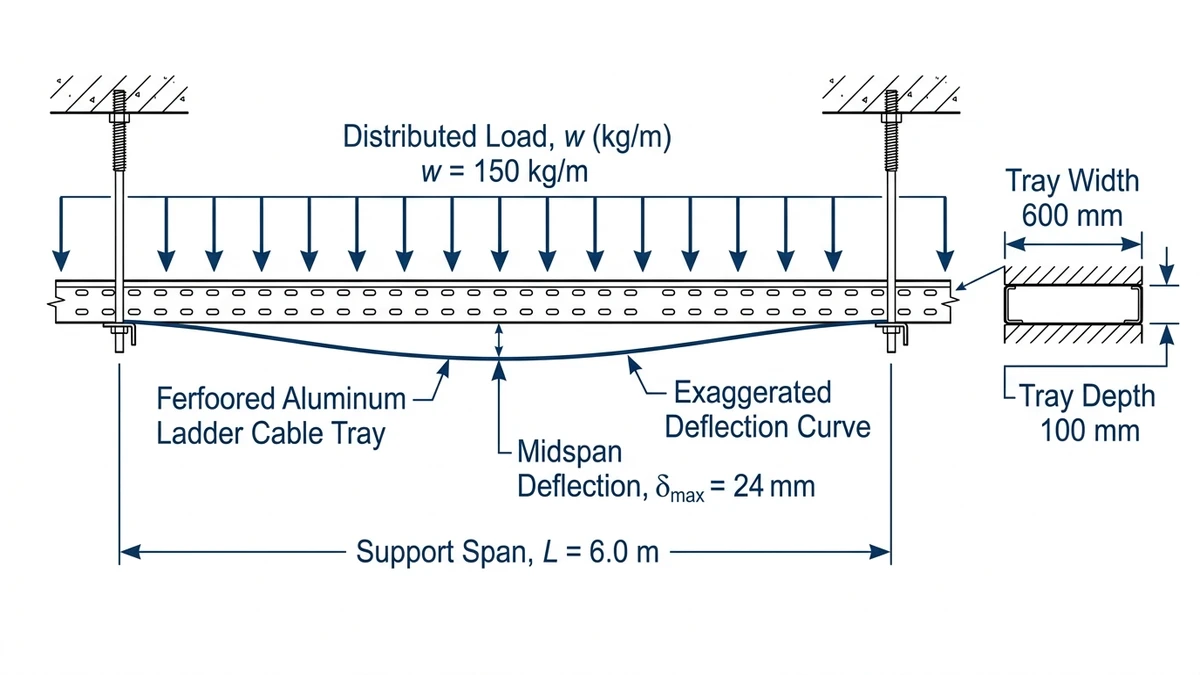
Figure 2. Engineering diagram of a ladder cable tray span showing tray width, depth, distributed load in kg/m, support span, and resulting deflection for sizing in data centers.
[Expert Insight]
– Where we have standardized on a 2.5 m span instead of 3.0 m, structural coordination became easier: identical brackets and predictable midspan clearance simplified clash checks with ductwork and sprinkler mains.
– Testing on long battery runs showed that even modest midspan deflection can loosen cleats over time; specifying a stiffer tray profile and shorter span reduced re-torque visits in the first year of operation.
Applying Tray Choices to Real Data Hall Layouts
Selecting a cable tray system for a data center is only half the job; you also have to route it through real data halls with column grids, hot‑aisle/cold‑aisle arrangements, and expansion plans. The governing parameters are aisle alignment, vertical stacking, and separation of power and low‑voltage trays.
Typical Routing Patterns Over White Space
Most modern data halls use orthogonal runs following the rack grid:
Main distribution “highways” run perpendicular to rows, typically 10–20 m between electrical rooms and pod entries.
Branch trays run along the row length, often 8–14 m, feeding each rack pair.
A common pattern is ladder tray at 400–600 mm width above hot aisles for power, with wire mesh tray at 200–300 mm above cold aisles for low-voltage. Keeping at least 300 mm vertical separation (finished floor to tray centerline difference) and 150–200 mm horizontal offset between power and data trays reduces crosstalk and simplifies future upgrades.
Design consequence: once you pick ladder vs wire tray and width, you effectively lock in rack positions and PDU tap-offs. Re‑routing a 20 m power highway after the fact is far more disruptive than re‑filling it, so selection should assume 30–40 % spare fill.
Field Scenario: 2.4 m Aisle, 6 m Column Grid
Consider a hall with a 6 m column grid and 2.4 m hot/cold aisles:
Main power ladder tray (500 mm wide, 3 m support span) runs down the column line. At 70 kg/m cable load plus 10 kg/m tray mass, you’re at ~80 kg/m; that demands checking against at least an 80–100 kg/m load class to keep deflection within L/200 under IEC 61537.
Low‑voltage mesh tray (300 mm wide) runs offset 0.6 m toward the cold aisle, with supports coordinated to avoid clashes with sprinklers and containment hardware.
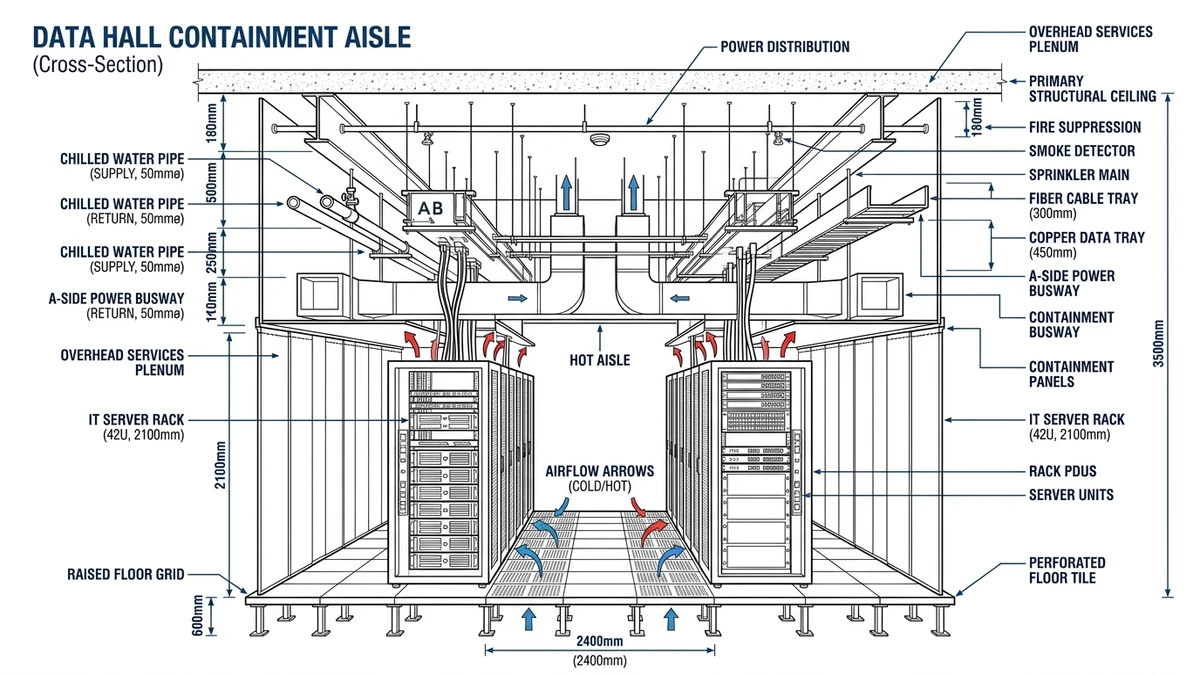
Selection consequence: choosing a heavier-duty ladder tray here can allow 3.0–3.5 m support spans instead of 2.0–2.5 m, which may eliminate an entire row of supports across a 30 m hall, reducing coordination with structural and fire systems.
Figure 3. Coordinated section of a data hall illustrating vertical separation between power trays, low-voltage trays, busway, and HVAC ducts above rack rows.
Coordinating with Related Systems and Standards
Cable tray systems in data centers sit in the middle of several design domains: structural, electrical protection, EMC, and fire strategy. The tray choice has knock-on effects in all of them, so selection should reference standards and adjacent systems, not just catalog ratings.
Structural and Seismic Coordination
Tray mass plus cable load feeds into building support design:
For overhead mounting, verify the base plate and anchor bolts against the combined distributed load and any expected seismic acceleration.
In regions with seismic design requirements, using braced trapeze hangers and limiting spans to 1.5–2.0 m on major runs generally reduces sway and helps retain clearances.
In our reviews of retrofit projects, under-designed trapeze hangers have been a recurring issue; once trays are fully populated, deflection and sway become evident during maintenance or minor seismic events, forcing costly reinforcement.
Electrical Protection and EMC
Tray material, bonding, and routing interact with protective devices and EMC performance:
Metallic trays typically form part of the bonding network. Ensure continuity with bonding jumpers across expansion joints and fittings.
When trays run parallel to sensitive LV circuits, use solid-bottom or perforated trays with covers, and maintain separation from high-harmonic or rapidly switching loads.
IEC 61537 covers mechanical and electrical continuity tests for cable tray systems; referencing its test routines in specifications provides a common basis for tray selection and inspection (see IEC 61537:2016, clauses on electrical continuity and load testing: IEC 61537 publication page).
Fire Strategy and Escape Routes
Tray selection and routing influence fire performance and egress:
Where trays cross escape routes, check clearance and consider fire-resistant fixings or separate supports independent of non-fire-rated ceilings.
Covers and solid bottoms can help limit flaming droplet risk but will concentrate heat; match cable fire performance to the expected thermal environment and derate if necessary.
How Xinma Helps Coordinate Tray Selection, Loading, and Support Details
Xinma ties data center cable tray selection directly to the design variables that drive reliability: load class, span, fill ratio, and thermal margin. For dense 600 mm power ladders spanning 3.0 m under 75–120 kg/m distributed load, those variables decide whether the system remains within IEC 61537 deflection and ampacity assumptions or creeps into risk as circuits are added.
From the choices outlined earlier—ladder vs wire mesh, 300 mm vs 900 mm width, 1.5 m vs 3.0 m support spans—Xinma’s role is to check the combination, not just the catalog part. That includes:
Verifying load class vs actual cable mass (for example, 40–60 kg/m low-voltage bundles plus 20–30 kg/m power) for each route.
Reviewing support spacing and midspan deflection against the selected tray height and steel thickness.
Checking cable fill vs derating, especially where trays stack in 2–3 layers or run above 30 °C ambient in ceiling voids.
Coordinating fittings (tees, offsets, reducers) so concentrated loads and change-of-direction points stay within span and support limits.
In our coordination reviews with designers, we often find that simply tightening the standard span from 3.0 m to 2.5 m and locking in a higher load class tray eliminates later requests to “double up” runs or restrict additional circuits.
If you are at the stage of locking in tray families, Xinma can review your tray layouts, loading assumptions, and support drawings and provide specification notes or redlines so the installed system behaves like the one you calculated. For projects that need integrated power distribution, that coordination can extend to busway runs feeding PDUs and RPPs so tray capacity, bus plug positions, and cable exit points align from the start.
To explore tray families and load classes suitable for dense data centers, you can review Xinma’s main cable tray range, including heavy-duty options for primary distribution: cable tray systems overview. Where routes favor open ladder designs for heat dissipation and fault restraint, see the dedicated ladder cable tray selection. For coordination with overhead power distribution, Xinma’s busway solutions for data halls can be evaluated alongside tray layouts to balance tray fill, drop lengths, and tap-off locations.
How do I size cable tray width for mixed power and data runs in a data center?
Calculate the total cable cross-sectional area for each route, apply a typical fill limit of about 40 % for power and 60 % for data, then choose the next standard tray width that keeps both within those limits with at least 20–30 % spare capacity for growth.
When should I choose ladder tray instead of wire mesh above racks?
Use ladder tray when you have heavy power feeders, higher fault levels, or the need for strong cleating; reserve wire mesh for lighter low-voltage bundles where frequent reconfiguration and many drop-outs are expected.
How much separation is usually needed between power and network trays?
A practical starting point is 150–300 mm horizontal separation with some vertical offset when trays share supports, increasing distance or adding metallic barriers if you have high-harmonic loads or very sensitive data circuits.
How does support span affect cable tray cost and performance?
Longer spans reduce hanger quantity but increase deflection and lower allowable load, while shorter spans add hardware cost yet improve stiffness, headroom control, and long-term stability of cleats and ties.
What should I check before routing cable trays across escape routes?
Confirm clear headroom under full cable load, verify that supports and fixings meet the project fire strategy, and consider independent bracing so deformation of adjacent services does not compromise the escape path.
Kevin Zheng
Kevin Zheng is a manager linked to Shanghai Xinma Busway & Cable Tray Co., Ltd. He writes technical content on cable tray systems, installation practice, sizing logic, load classes, and related standards for industrial and infrastructure applications.