Selecting an outdoor cable tray starts with identifying the route’s main failure risk. In exposed service, problems usually begin at joints, supports, covers, and damaged finishes rather than in straight sections, so selection should balance corrosion severity, mechanical loading, thermal behavior, and maintenance access. Use IEC 61537 as the structural testing reference and NEMA guidance to confirm application fit.
For specifiers and engineers, the key question is: what will govern this route in service—heat, corrosion, wind, or contamination? That answer sets tray type, material, support spacing, cover use, and detailing.
What Conditions Matter Most in Outdoor Cable Tray Selection?
An outdoor cable tray should be chosen for the harshest real exposure along the route, not the average. Many poor selections are structurally acceptable on paper but mismatched to chlorides, solar heating, or wind uplift.
Site-condition checklist
Before specifying any outdoor cable tray, define these conditions:
Corrosion environment
Inland industrial, coastal, chemical washdown, or mixed exposure
Salt spray influence, often higher risk within about 1 km to 5 km of shoreline
Chlorides, sulfur compounds, fertilizer dust, or standing water
Temperature exposure
Design ambient range, for example -20 °C to 50 °C
Solar heating on exposed metal or dark covers
Whether cable ampacity derating will be required
Wind and uplift
Open roof, pipe rack, façade, or elevated steelwork
Need for covers, cover clamps, and shorter support spans
Need for drainage, ventilation, or protection from below
Maintenance access
Frequency of cable additions and troubleshooting
Inspection interval, often 6 to 12 months in exposed industrial runs
Whether covers will slow fault-finding or routine inspection
What each condition changes
Corrosion usually drives material choice first, while temperature affects fill and ampacity. Wind matters more once covers are added, and water or debris determines whether open ventilation or more enclosure is the better tradeoff.
Outdoor failures typically start at cut edges, bolted joints, and cover hardware, so installed-system durability matters more than straight-run catalog strength. Even one rooftop, washdown, or coastal segment may justify upgraded fittings or stainless sections.
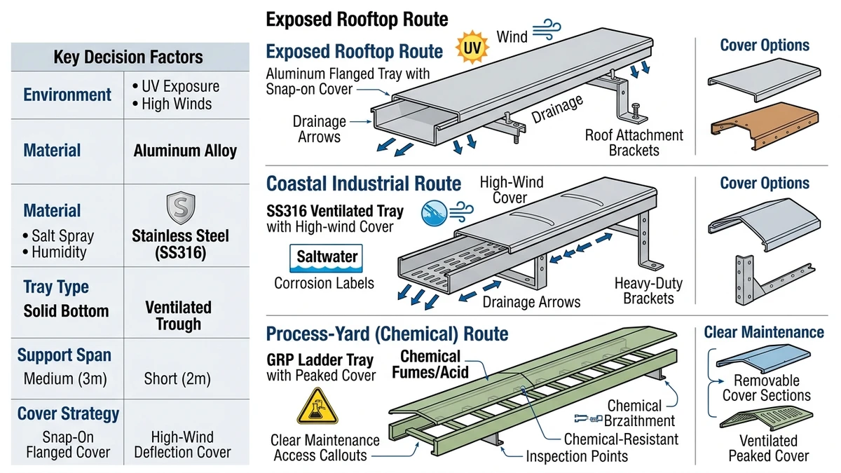
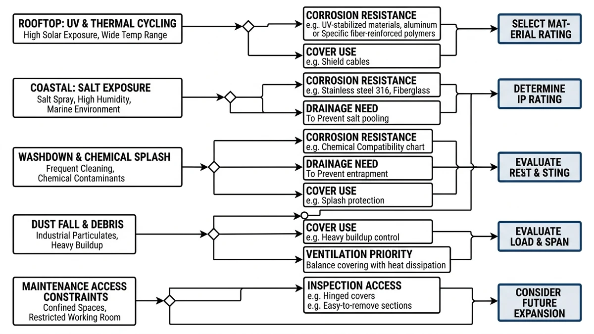
Figure 1. Outdoor cable tray selection map connecting rooftop, coastal, washdown, and dusty environments to drainage, corrosion, and access requirements.
Which Tray Type Works Best Outdoors: Ladder, Perforated, or Solid-Bottom?
For exposed power routes, ladder tray is usually the safest outdoor baseline because it drains well, cools best, and often allows longer spans. Perforated tray is the middle option for smaller cables needing more continuous support, while solid-bottom tray is a targeted choice where contamination control outweighs thermal and drainage limits.
Engineering comparison of outdoor tray types
Parameter
Ladder tray
Perforated tray
Solid-bottom tray
Airflow / heat dissipation
Highest
Moderate
Lowest
Rainwater drainage
Excellent
Good if perforations remain open
Limited unless drains are detailed
Debris protection
Low without covers
Moderate
High from below
Suitability for heavy power cables
Usually best
Good for medium loads
Often constrained by thermal margin
Support for small cables
Lower without accessories
Better continuous support
Best continuous support
Inspection and cleaning
Easiest
Good
Harder where dirt or moisture accumulates
Corrosion tendency in wet service
Lower if water drains freely
Moderate
Higher if water ponds
Typical support span tendency
About 2.0 m to 3.0 m
About 1.5 m to 2.5 m
Often shortest at similar width/gauge
Best use case
Exposed power routes, hot climates, long runs
Mixed services, moderate debris
Fine cables, splash-prone or dust-sensitive zones
How the choice changes system behavior
Tray type is mainly a tradeoff between ventilation, shielding, and maintenance. A solid-bottom tray protects better, but if sun and cable grouping raise internal temperature by 10 °C to 15 °C, allowable fill may drop or conductor size may need to increase.
Use when / avoid when / check before specifying
Use ladder tray when
Use ladder tray when thermal performance, drainage, or longer support spans matter most. It is often the best default for roofs, pipe racks, and exposed utility corridors.
Use perforated tray when
Use perforated tray when smaller cables need more continuous support but the route still needs drainage and some airflow. It is often suitable for mixed-service outdoor runs.
Use solid-bottom tray when
Use solid-bottom tray when contamination from below, splash, or fine-cable support clearly outweighs the loss of ventilation. It is usually more appropriate for instrument or control wiring than for heavily loaded exposed power runs.
Avoid these mismatches
Avoid solid-bottom tray on hot, fully exposed routes unless thermal checks confirm enough margin. Avoid open ladder where falling debris or small-cable support is the controlling issue.
Check before specifying
Check cable fill, solar exposure, maintenance interval, and cover requirements together. A tray may be structurally adequate yet still be the wrong outdoor cable tray if heat buildup or debris retention becomes the real limit.
[Expert Insight]
If the run is both hot and wet, start with ladder tray and only move toward a more enclosed form if contamination control is genuinely required.
If future cable additions are likely, preserve thermal margin early.
Evaluate bends and reducers as carefully as straight sections, because outdoor failures often begin there.
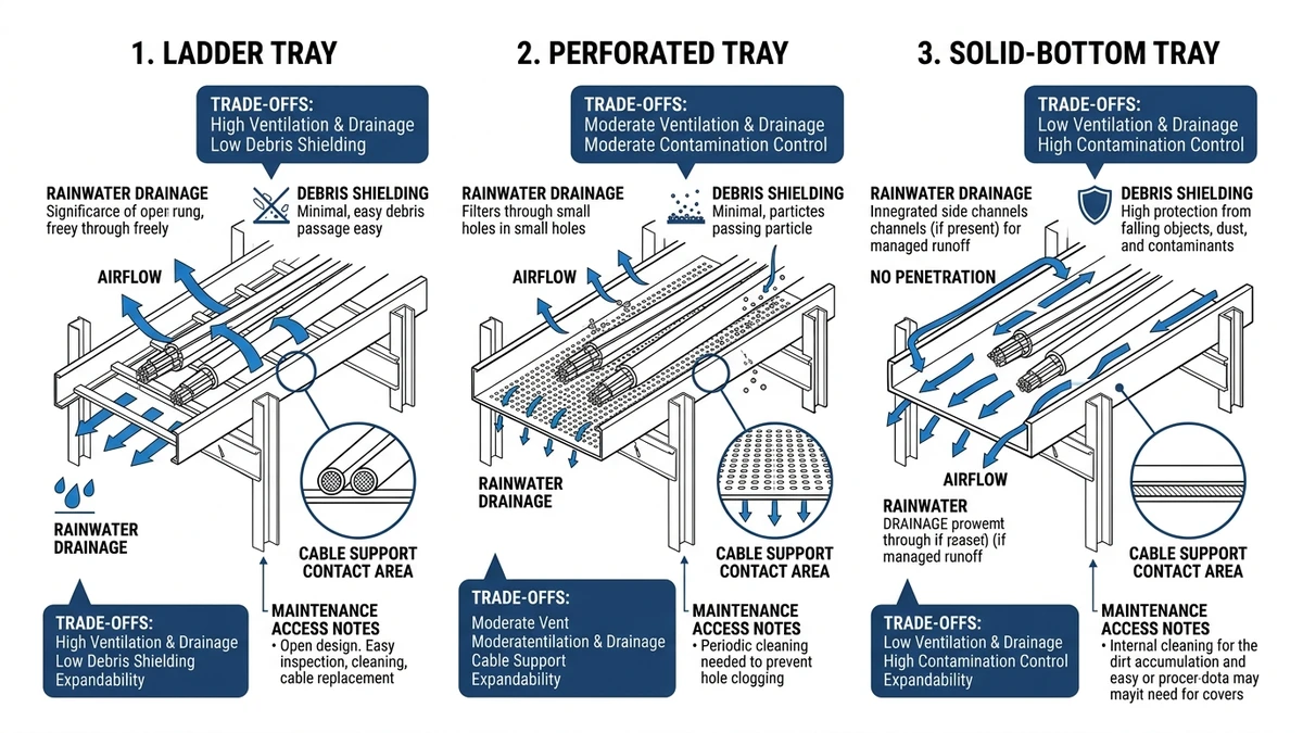
Figure 2. Comparison of ladder, perforated, and solid-bottom tray forms for outdoor drainage, ventilation, contamination control, and inspection speed.
How Do Material, Finish, and Corrosion Exposure Change the Decision?
Material choice determines how well the outdoor cable tray retains mechanical capacity, bonding continuity, and fastening integrity under weather exposure. Corrosion outdoors often starts at cut edges, splice plates, supports, and mixed-metal interfaces, especially where moisture remains.
What drives corrosion risk
The main variables are chloride level, pH, wet-dry cycling, temperature, and moisture retention. IEC 61537 covers mechanical and corrosion-related performance for cable tray and cable ladder systems; see IEC 61537: Cable management — Cable tray systems and cable ladder systems: IEC 61537 publication page
Lower stiffness than comparable steel profiles; galvanic detailing needed
Long rooftop runs need lighter support loads
Chemical washdown or aggressive process area
316L stainless or coated system
Better resistance to wet cycling and chemicals
Coating damage can localize attack; stainless cost remains higher
Process chemistry governs service life
What the numbers mean in practice
Material selection changes both corrosion life and structural behavior. Aluminum can reduce dead load by roughly 30% to 50% versus similar steel tray, while hot-dip galvanized steel remains practical for ordinary outdoor exposures but is less attractive where chlorides, washdown, or trapped moisture dominate.
Use when / avoid when / check before specifying
Use galvanized steel when
Use hot-dip galvanized tray when the atmosphere is moderately corrosive, loads are significant, and periodic inspection is acceptable. It is often a balanced choice for inland industrial routes.
Use aluminum when
Use aluminum when dead load matters or rooftop handling is difficult. Its support spacing should be checked against deflection as well as strength.
Use stainless steel when
Use 316 or 316L stainless when chloride exposure, washdown, or low-maintenance service governs the decision. The higher initial cost is often justified where replacement would be disruptive.
Avoid these mismatches
Avoid pre-galvanized steel on fully exposed wet runs. Avoid mixing tray, supports, and hardware without checking galvanic compatibility, because tray material alone does not control corrosion performance.
Check before specifying
Check the full system: couplers, bolts, support steel, bonding jumpers, and cover clamps. In service, these parts often deteriorate before the straight tray lengths.
[Expert Insight]
Near coastlines, distance from shore is only a starting indicator; wind direction and moisture pockets can matter more.
If aluminum tray is selected, review stiffness as well as strength.
For corrosive service, fittings should match the tray exposure class.
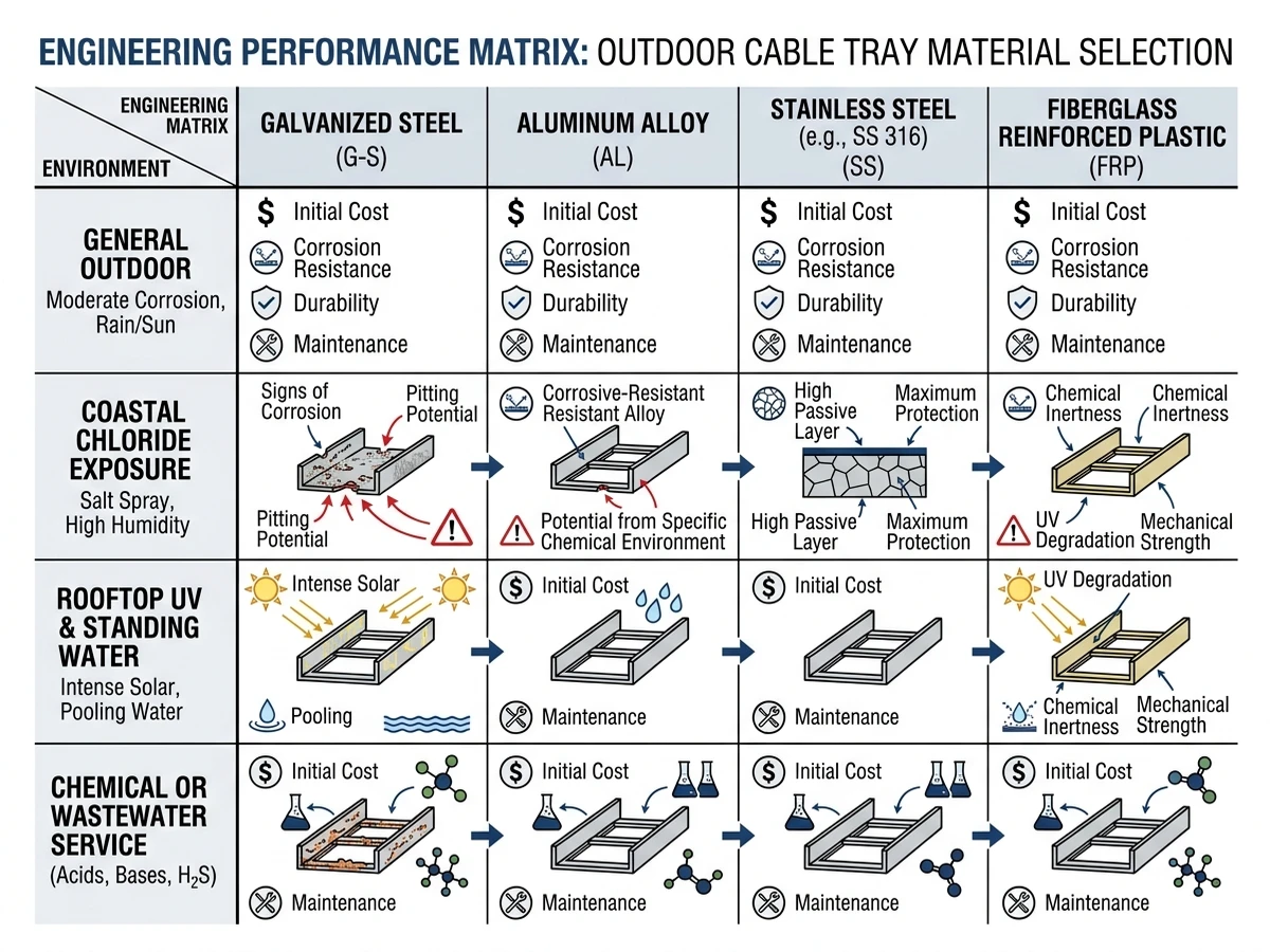
Figure 3. Material selection matrix comparing galvanized steel, aluminum, stainless steel, and FRP across coastal, rooftop, chemical, and general outdoor exposures.
What Structural and Thermal Checks Should Not Be Skipped Outdoors?
The most common reason an outdoor cable tray changes during review is that the initial selection did not reflect the real installed load. Outdoors, the tray carries cable weight, self-weight, covers, and fittings while also seeing wind, vibration, and solar heating.
Structural checks that change tray selection
Start with the actual service load in kg/m, including cables, tray self-weight, covers, accessories, and any point loads. Support span is often in the 1.5 m to 3.0 m range, but cover weight on wider trays can reduce allowable spacing or increase deflection.
Thermal checks that affect cable loading
Outdoor thermal review should include solar gain, not just ambient air temperature. On unshaded runs, solar exposure can raise tray metal temperature by about 15 °C to 25 °C above ambient, which can reduce cable heat rejection and lead to ampacity derating, lower fill, or a larger tray.
Minimum outdoor engineering checklist
Verify installed load
Confirm the tray load class against the full installed load in kg/m, not cable weight alone.
Check real-span deflection
Use actual support spacing, cover weight, and fittings layout. Do not rely only on the nominal catalog span.
Review wind uplift
Where covers or solid-bottom sections are used, evaluate uplift and side load on brackets, hold-downs, and splice joints.
Account for thermal expansion
Movement becomes significant on long metallic runs, often beyond about 30 m. For steel, a 30 m run with a 40 °C temperature swing can expand by about 14 mm.
Recheck ampacity and fill
For design ambient conditions of 40 °C to 50 °C plus solar exposure, confirm that cable fill and grouping still leave adequate thermal margin.
Validate fittings and restraint
Reducers, vertical bends, expansion joints, and cover clamps should follow the same load path and corrosion logic as the tray straights.
The key point is that outdoor cable tray selection is a coupled problem: the tray with the best structural margin may create a thermal penalty, while the tray with the best cooling may need more restraint or cable-support accessories.
What Outdoor Installation Details Usually Decide Long-Term Reliability?
Long-term reliability is usually decided by detailing rather than by tray model alone. Drainage, cut-edge protection, thermal movement, and inspection access often have more effect on service life than small catalog differences.
Detail the route for drainage
Horizontal runs should not trap water at couplers, cover laps, or low points. Even a slight fall of 1° to 2° can improve drainage and reduce corrosion risk.
Treat covers as a structural and thermal item
Covers reduce UV, rain entry, and debris, but they also add dead load and reduce ventilation. If cable fill is already above about 40%, the thermal effect should be checked before covers are applied across the route.
Protect cut edges and holes immediately
Once drilling or cutting breaks the factory finish, corrosion often starts there. For galvanized systems, zinc-rich repair or the manufacturer’s approved touch-up method should be part of the installation requirement.
Match hardware and supports to the tray material
Mixed-metal details can accelerate corrosion in wet service. Hardware, brackets, and supports should therefore be reviewed with the tray material, not selected separately.
Allow for thermal movement
Expansion splice plates or fixed/guide support logic should be planned before installation. Outdoor runs in full sun do not behave like indoor runs.
Review uplift and restraint
Wind can loosen covers and stress hold-down clips, especially on exposed roofs. Support systems sized only for gravity load may be inadequate.
Preserve access at transitions
Reducers, risers, equipment entries, and terminations should remain inspectable and serviceable. If a route cannot be opened, drained, or re-secured easily, maintenance issues usually appear there first.
In service, the most reliable outdoor cable tray routes are the ones detailed for drainage, coating continuity, movement, and access from the start.
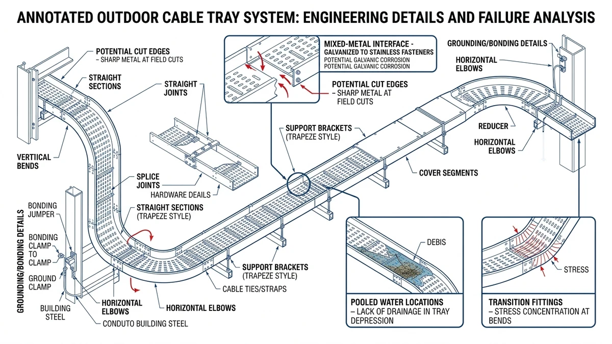
Figure 4. Annotated outdoor tray run identifying common reliability weak points at splice joints, supports, covers, transitions, and cut edges.
How to Coordinate the Specification as a Complete Outdoor Cable Tray System
A good specification treats the outdoor cable tray as one coordinated system: tray type, width, side rail height, material, covers, fittings, supports, and restraints all interact. A wider tray may improve separation but increase wind area, and a cover may protect against contamination while adding 3 kg/m to 8 kg/m of dead load.
What should be checked together
At minimum, the review should confirm:
Tray loading basis in kg/m, including cable and covers
Support span and deflection target
Corrosion exposure and finish selection
Fittings continuity at bends, tees, reducers, and risers
Bonding and grounding continuity at splices and transitions
Access for maintenance, drainage, and future cable additions
If you are comparing tray families, use a system view rather than isolated product data. Xinma’s cable tray systems overview is a useful starting point for understanding how tray configurations are organized across different applications. For projects where the route is clearly power-heavy and exposed, reviewing the structural form of a ladder tray solution can help align ventilation and span expectations early. Where the cable mix includes smaller conductors needing more continuous support, a perforated tray option is often the more relevant comparison.
Specification quality also depends on installation and sizing logic. Before release, many engineers cross-check span assumptions against a support layout guide and verify width and fill assumptions using a tray dimension reference.
A technical, consequence-driven next step
If the route includes mixed exposures—such as rooftop sun, coastal air, and process-area washdown—coordinate loading, access, corrosion class, and fittings before the package is locked. That reduces late changes when covers add load, fitting finishes do not match the tray, or thermal derating forces a wider section after supports are fixed.
Xinma can support that review as a system-coordination exercise rather than a product-only discussion. The useful output is a tray schedule that stays consistent from straight lengths to bends, supports, hold-downs, and corrosion detailing.
Frequently Asked Questions
How do I choose the right outdoor cable tray material?
Start with the exposure mechanism rather than the tray label. Inland weather may suit hot-dip galvanized steel, while chloride-heavy, washdown, or coastal service often pushes selection toward 316/316L stainless steel or carefully detailed aluminum.
Is ladder tray better than perforated tray for outdoor use?
Ladder tray is often preferred for exposed power routes because it drains well and rejects heat more effectively. Perforated tray can still be the better choice where smaller cables need more continuous support and debris levels are manageable.
Do outdoor cable trays need covers?
Not always. Covers help with UV, rain, and debris, but they also add load and can reduce cooling, so they should be used where the protection benefit outweighs the thermal and structural penalty.
How far apart should outdoor cable tray supports be?
Support spacing depends on tray type, load class, width, material, and whether covers are used. Many outdoor layouts fall in the 1.5 m to 3.0 m range, but the final value should come from the tested tray rating and installed load.
Does sunlight affect cable tray performance?
Yes. Solar exposure may raise tray temperature above ambient, which reduces cable thermal margin and makes fill or ampacity checks more important on exposed runs.
What usually fails first in a harsh outdoor tray installation?
The first issues are often found at joints, cut edges, supports, and cover hardware rather than in the straight tray sections. That is why fittings, finish repair, and restraint details deserve as much attention as tray width and load rating.
Kevin Zheng
Kevin Zheng is a manager linked to Shanghai Xinma Busway & Cable Tray Co., Ltd. He writes technical content on cable tray systems, installation practice, sizing logic, load classes, and related standards for industrial and infrastructure applications.