A marine cable tray is a cable management system for ships, offshore platforms, coastal plants, and splash-zone areas where salt spray, humidity up to about 95% RH, vibration, and temperature swings from roughly −20 °C to +60 °C affect both corrosion and structural support. Under IEC 61537, trays are assessed as mechanical systems, but marine selection also has to satisfy class rules and project requirements for material grade, coating, support spacing, and fastening details.
Unlike dry indoor installations, marine trays are selected not only for cable capacity but for whether they remain structurally sound, electrically continuous, inspectable, and maintainable in the actual exposure zone. Trays that perform adequately inland may corrode at joints, fail at cut edges, or loosen under motion on exposed decks or in washdown machinery spaces. For related configurations and system context, see Xinma’s overview of cable tray systems and its main cable management product range.
Which Materials Are Used for Marine Cable Tray, and How Do They Behave in Salt Exposure?
Material choice in marine cable tray design is mainly a corrosion-control decision. In chloride-rich air, early failures usually start at cut edges, bolted joints, fasteners, and wet crevices rather than along straight side rails.
Material comparison in salt exposure
Material
Typical marine behavior
Main advantages
Main limitations
Use when
Avoid when
Check before specifying
Hot-dip galvanized steel
Zinc provides sacrificial protection, but chlorides consume the coating faster at damaged areas and fixings
Lower initial cost, good stiffness, familiar support hardware
Coating life drops in splash, washdown, or standing-salt conditions
Sheltered interior spaces with inspection access
Open decks, frequent washdown zones, persistent salt deposits
Coating thickness, repair method at cut edges, fastener compatibility
Stainless steel 304
Better than galvanized steel in mild humidity, but vulnerable to pitting and crevice corrosion in chlorides
Good finish, moderate maintenance in mild atmospheres
Usually not preferred for direct salt spray or stagnant deposits
Interior spaces with controlled condensation
Splash zones, deckhead runs near seawater exposure
Lower stiffness in some systems, UV and fire performance must be checked
Highly corrosive topsides, chemical washdown areas
Heavy-load long spans without verified support data
Fire performance, UV resistance, support spacing, impact duty
What changes the engineering decision
The main trade-off is durability, stiffness, and tolerance to detailing errors. In direct salt spray, frequent washdown, or where wet salt remains for more than about 24 hours, galvanized steel often becomes maintenance-driven, while 316/316L stainless or FRP/GRP is usually safer.
One quantified example that changes the choice
Material also affects support design. On runs with support centers around 3.0 m to 6.0 m, aluminum’s lower weight can reduce bracket and deck loading, but galvanic isolation still has to be designed as part of the full tray and hardware package.
[Expert Insight]
– A corrosion-resistant side rail does not compensate for the wrong fastener set. Marine failures often start where small hardware creates a local cell.
– When maintenance access is limited, life-cycle cost usually favors the material that reduces intervention frequency, not the material with the lowest purchase price.
– If a route changes from sheltered interior space to exposed deck, treat that as a material transition point rather than carrying one material spec through the whole run.
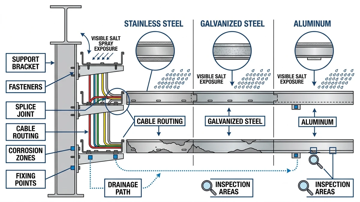
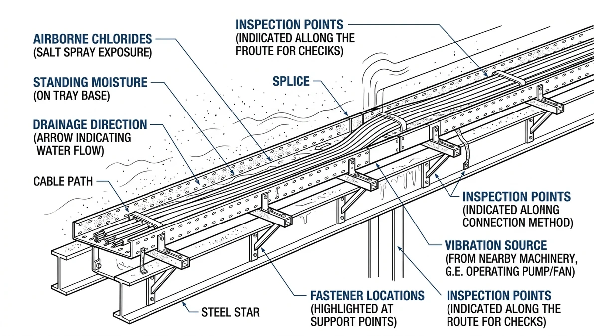
Figure 1. Marine cable tray exposure map highlighting salt deposition, standing moisture, vibration zones, and common corrosion-prone joint locations.
How Corrosion Damages Marine Cable Tray Systems in Real Installations
Marine cable tray systems usually degrade by localized corrosion, not uniform metal loss. Chlorides, moisture, oxygen differences, and dissimilar metals attack fasteners, cut edges, welds, and water-trap zones first, and even 10% to 20% section loss at a side rail or splice can materially reduce load capacity.
Chloride attack and passive-film breakdown
Stainless steel depends on a passive oxide film, but chlorides can break it locally and start pitting or crevice corrosion. Because salt deposits can remain active above about 75% RH, drainage and simple geometry are often more effective than thicker metal alone.
Galvanic corrosion at joints and supports
Galvanic corrosion occurs when dissimilar metals are electrically connected in the presence of an electrolyte. A common case is galvanized tray fixed with stainless hardware on a wet deckhead, where zinc is consumed faster around the contact area.
Crevice, under-deposit, and water-trap corrosion
Geometry often controls the failure point because washers, overlaps, terminations, and flat runs with poor fall create oxygen-starved wet crevices. Early corrosion is often found in the lowest 50 mm to 100 mm of a run, near penetrations, or under retained debris.
What to inspect first
In aggressive marine zones, inspection intervals are often reduced to around 6 to 12 months, especially where cut edges, coating damage, or mixed-metal fixings exist. First checks should focus on joints, supports, field modifications, and low points where water or deposits collect.
Joints and splice plates
These combine crevices, fasteners, and load transfer, so they are usually higher-risk than straight tray lengths.
Supports and bracket interfaces
Support connections often stay wet longer than the tray body and are common galvanic contact points.
Cut edges and field modifications
Field drilling and cutting remove protective finishes and often create the earliest corrosion cells.
Low points and drainage restrictions
Even shallow standing water can keep corrosion active if salts remain trapped.
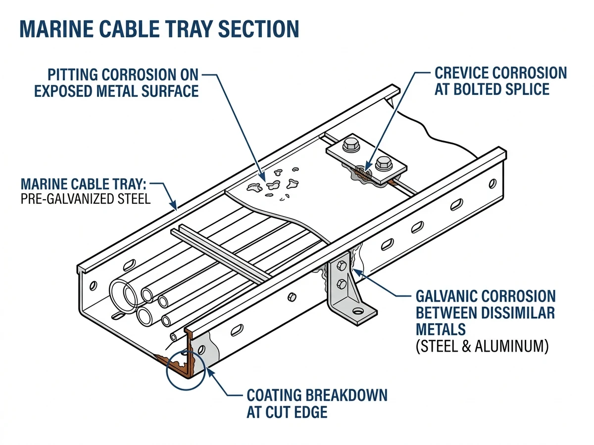
Figure 2. Corrosion mechanism detail for marine cable tray systems showing pitting, crevice attack, galvanic contact, and damaged protective finishes.
Which Tray Type Works Best in Marine Conditions: Ladder, Perforated, or Solid-Bottom?
In marine conditions, tray type should be chosen by drainage, salt retention, cable support density, heat dissipation, and physical protection. For most exposed runs, ladder tray is the default because it drains quickly and retains the least salt; perforated tray is a compromise; solid-bottom tray is usually justified only when shielding or debris protection outweighs the corrosion and thermal penalty.
Engineering comparison
Parameter
Ladder tray
Perforated tray
Solid-bottom tray
Drainage after spray or washdown
Excellent
Good
Poor unless sloped and drained
Ventilation and heat dissipation
Excellent
Moderate to good
Lowest
Salt and moisture retention
Lowest
Moderate
Highest
Mechanical protection
Lowest
Moderate
Highest
Cleaning and visual inspection
Best
Good
Worst
Typical support spacing tendency
Often longest, about 1.5 m to 3.0 m depending on load class
About 1.5 m to 2.5 m
Often shortest for similar sheet thickness and load
Best marine use
Power feeders, open runs, long exposed routes
Mixed service, control and instrumentation
Short protected sections, contamination shielding
Ladder tray: use when drainage matters most
Ladder tray sheds water, dries quickly, and improves cable cooling. It is usually the best option for exposed routes, frequent washdown, and thermally loaded runs.
Perforated tray: use when smaller cables need more continuous support
Perforated tray gives control and instrumentation cables more continuous bottom support than ladder tray. Its trade-off is higher residue retention, so it suits marine interiors or routes with workable cleaning access.
Solid-bottom tray: use only when protection justifies the penalty
Solid-bottom tray can protect cables from debris or drips, but it also traps moisture and reduces cooling. On long exposed runs, especially with cable fill above about 40% to 50% in machinery spaces around 45 °C to 55 °C, both thermal derating and corrosion risk increase.
Decision logic
Use ladder tray when
The route is exposed, washdown is frequent, heat dissipation matters, or inspection access is important.
Use perforated tray when
Smaller cables need more continuous support, but the route still requires drainage and moderate ventilation.
Avoid solid-bottom tray when
The run is long, salt-exposed, thermally stressed, or difficult to inspect and clean.
Check before specifying
Confirm tray type against IEC 61537 load class, actual support span, cable fill, ambient temperature, and project fire or shielding requirements. For applications where open-run corrosion resistance and span efficiency are priorities, Xinma’s ladder tray configurations are typically the first comparison point; if the route needs more continuous bottom support, review perforated tray options against the added cleaning trade-off.
[Expert Insight]
– The tray that offers the most physical protection is not usually the tray that performs best against marine corrosion.
– If two tray types meet the load requirement, the one that drains and dries faster often gives the longer maintenance interval.
– For instrumentation-heavy routes, the right compromise is often not a stronger tray but a tray with better support density and a cleaner inspection plan.
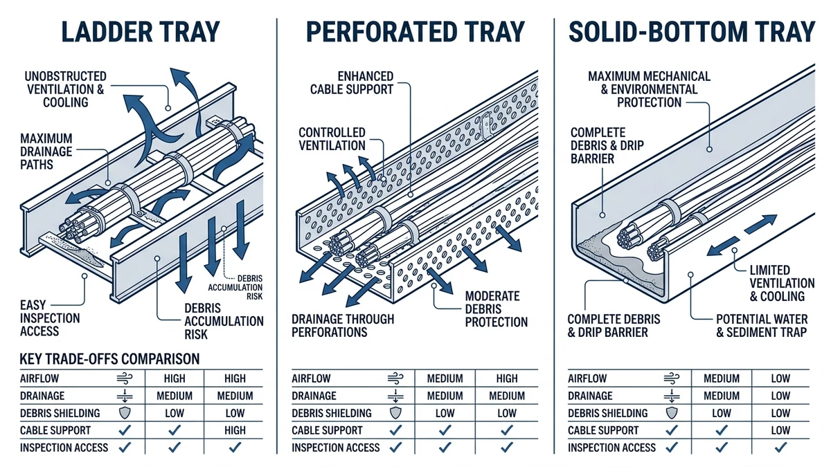
Figure 3. Marine tray type comparison showing ladder, perforated, and solid-bottom forms with drainage, ventilation, and support trade-offs.
What Fixing Requirements Matter Most for Marine Cable Tray Installations?
Marine cable tray installations usually succeed or fail at the fixing points. Supports, clamps, anchors, and fasteners must carry dead load, motion, vibration, and thermal movement while maintaining corrosion resistance and clamp force.
Support spacing and load path
Support spacing should come from tested IEC 61537 tray data, not generic inland practice. In marine work, spans of about 1.5 m to 3.0 m are common, depending on tray width, side rail depth, tray type, and installed load in kg/m.
Fastener and bracket selection
Marine fixings must resist both corrosion and loosening, so stainless hardware of the correct grade and vibration-resistant locking details are typical. Main support fasteners are commonly M8, M10, or M12, selected from bracket reaction and support thickness rather than habit.
Movement and restraint
Rigidly fixing every support is a common error. Over a 30 m straight run, normal thermal movement can reach several millimeters, and without sliding supports or expansion allowance the tray can bow, overload end fixings, or transfer force into cable cleats.
Practical checklist before release
Before release, verify full installed load in kg/m, set support span from tested data, and check deflection criteria such as L/200 where applicable. Add supports near elbows, tees, reducers, and vertical transitions, often within about 300 mm to 600 mm where system details require it; also avoid mixed-metal contact without isolation and support locations that block inspection. Where fittings and support interfaces are part of the design package, Xinma’s pages on tray fittings and connection pieces and seismic and restraint support options help align straight-run assumptions with actual branch and restraint details.
Figure 4. Marine cable tray fixing detail showing support spacing logic, compatible fasteners, splice reinforcement, and drainage-aware mounting orientation.
Where Do Marine Cable Tray Designs Usually Go Wrong in the Field?
Most field failures trace back to four issues: wrong material pairing, underestimated installed load, poor movement allowance, and layouts that cannot be inspected.
Material pairing errors
Specifying “stainless” or “aluminum” without checking the exact exposure zone is a common shortcut. Even 316L can corrode in tight wet crevices, and aluminum in direct contact with carbon steel supports can suffer galvanic attack.
Span and load underestimation
Installed load often exceeds the design basis once covers, retained residue, and future cable additions are included. The first signs are usually excess deflection, loosened supports, or local overstress at fittings rather than immediate collapse.
Movement ignored
If thermal expansion and vessel motion are not considered together, trays can bow, clamp preload can fall, and end anchors can be overloaded. This is especially common when offshore details are copied from static onshore layouts.
Maintenance access designed out
Trays routed too close to bulkheads, pipework, or other obstructions are difficult to inspect and maintain. In aggressive zones that may need review every 6 to 12 months, poor access allows coating damage, trapped salt, and support corrosion to go unnoticed.
The practical lesson is to treat marine cable tray as an assembled system. Straight lengths, fittings, supports, fasteners, drainage, and inspection access all affect reliability.
How Xinma Helps Coordinate Material Choice, Corrosion Control, and Fixing Details
Marine cable tray specification works best when material, tray type, support span, fitting detail, and hardware are checked together before release. Many field corrections come from treating those items separately when a change in one variable affects the others.
Moving from galvanized steel to 316L stainless changes hardware compatibility and maintenance expectations. Adding covers increases distributed load and can reduce allowable support span, while switching from ladder to a more enclosed tray changes both cable cooling and corrosion behavior.
In specification-stage reviews for similar marine and coastal runs, the most useful checks are usually whether the tray material matches the actual exposure zone, whether fittings and hardware remain consistent with the corrosion strategy, whether support spacing reflects full installed load, whether bends and penetrations create water traps, and whether the layout can be inspected at its planned interval.
If you are defining tray width in mm, support span in m, material grade, and fixing hardware in one package, Xinma can help review those variables as one coordinated system rather than leaving conflicts to site installation. For sizing work before procurement, the technical references on tray width selection and broader busduct-versus-tray coordination through busway system planning can help when power distribution architecture affects the tray load and routing strategy.
Frequently Asked Questions
What is the main difference between a marine cable tray and a standard indoor tray?
Marine tray design is driven by salt exposure, humidity, vibration, and wet service conditions that affect both corrosion and support detailing. Indoor trays are often chosen mainly by load and routing, while marine trays usually require a combined review of material grade, hardware compatibility, drainage, and maintenance access.
Is 316 stainless steel always the best material for marine cable tray?
316 or 316L is often the preferred stainless option for chloride exposure, but it is not automatically the best choice everywhere. Weight limits, galvanic interfaces, fire performance, support spacing, and lifecycle maintenance can make aluminum or FRP/GRP more suitable in some locations.
When should ladder tray be used instead of perforated tray in marine environments?
Ladder tray is generally favored when drainage, ventilation, and easy washdown matter more than continuous bottom support. Perforated tray is often chosen where smaller cables need more support, provided the route can still be cleaned and inspected effectively.
How often should marine cable tray be inspected?
Inspection frequency depends on exposure severity, access, and material system, but aggressive splash or washdown zones are commonly checked more often than sheltered interior areas. A risk-based approach usually starts with joints, supports, cut edges, and low points where water or deposits collect.
What should be checked before specifying fasteners for a marine cable tray?
Check corrosion compatibility with the tray and support materials, expected vibration, required clamp force, and whether thermal movement requires sliding or fixed points. Bolt size, locking method, and bracket thickness should also match the actual reaction loads rather than a generic hardware schedule.
Can solid-bottom tray be used outdoors in marine service?
It can be used, but it is usually better reserved for short sections where shielding or debris protection is necessary. On long exposed runs, retained moisture and reduced ventilation often make it less forgiving than ladder or perforated tray.
Does coating thickness alone solve marine corrosion risk?
Usually not. Marine deterioration often starts at cut edges, joints, fastener interfaces, and trapped wet deposits, so detailing and material compatibility are as important as nominal coating thickness.
Kevin Zheng
Kevin Zheng is a manager linked to Shanghai Xinma Busway & Cable Tray Co., Ltd. He writes technical content on cable tray systems, installation practice, sizing logic, load classes, and related standards for industrial and infrastructure applications.