Address
304 North Cardinal St.
Dorchester Center, MA 02124
Work Hours
Monday to Friday: 7AM - 7PM
Weekend: 10AM - 5PM
Address
304 North Cardinal St.
Dorchester Center, MA 02124
Work Hours
Monday to Friday: 7AM - 7PM
Weekend: 10AM - 5PM
Get premium quality cable management systems directly from the manufacturer.
Fill out the form below to receive our catalog and pricing.
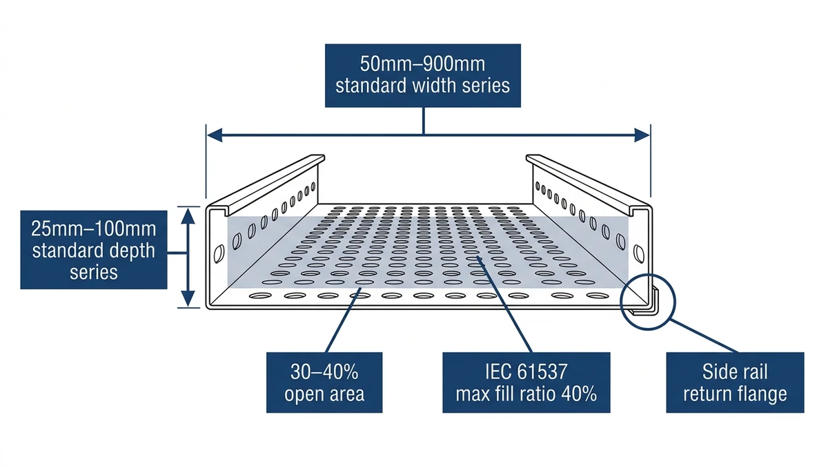
Perforated cable tray is a solid-bottom cable management channel with punched openings across its base and sidewalls, allowing airflow around cables while providing continuous support. For buyers in 2026, selecting the right width and depth directly determines cable fill compliance, thermal performance, and long-term system cost.
Unlike ladder-style trays, perforated trays distribute support across the full cable bed — making them the preferred choice for lightweight signal cables, instrumentation wiring, and data center horizontal runs where cables need protection from mechanical contact but also require ventilation. The perforations typically cover 30–40% of the tray surface area, reducing cable operating temperature through convective airflow. That airflow improvement feeds directly into ampacity derating calculations under IEC 61537 (cable management — cable tray systems and cable ladder systems).
Width governs how many cables can be laid side by side in a single layer. Depth controls how many layers can be stacked before fill ratio limits are exceeded. Get either one wrong and you’re either over-engineering the support structure or facing a mid-installation rework.
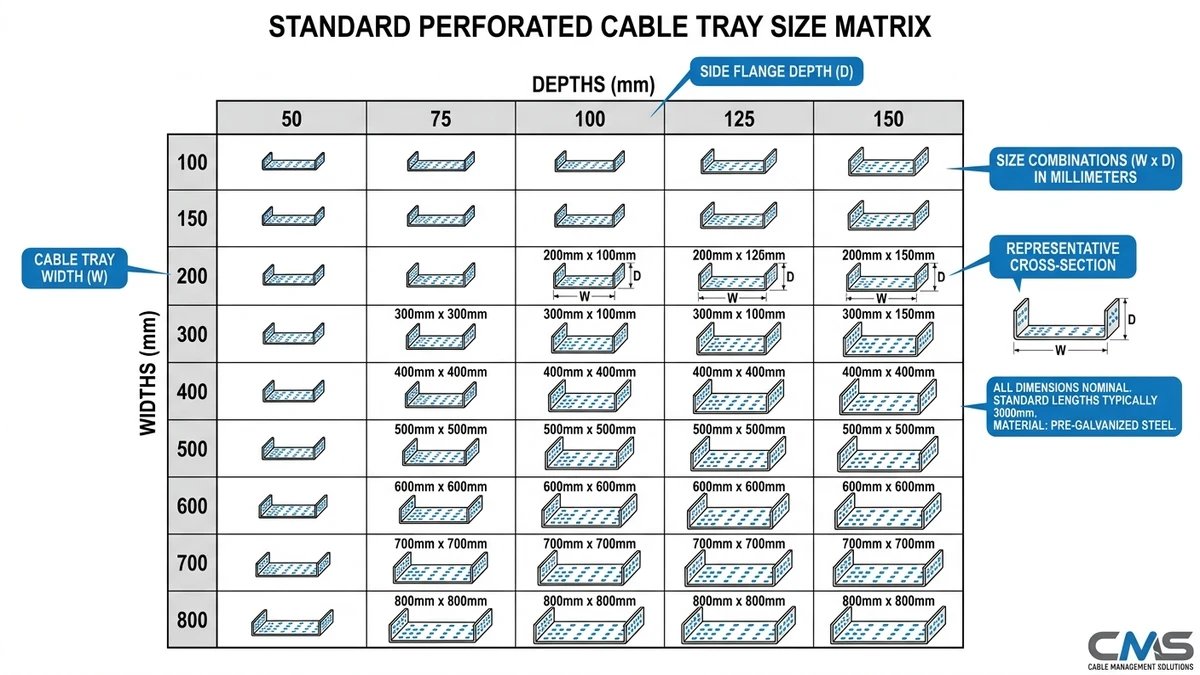
Standard widths run in incremental steps: 100 mm, 150 mm, 200 mm, 300 mm, 450 mm, and 600 mm are the most common in commercial and industrial cable management systems. A 100 mm tray handles light control wiring or a single power circuit; a 600 mm tray is sized for high-density cable routing in data centers or industrial plants where dozens of cables run in parallel.
The selection logic is fill ratio. IEC 61537 recommends a maximum fill ratio of 40% of the tray’s cross-sectional area for power cables, leaving room for heat dissipation and future additions. For a 300 mm wide × 60 mm deep tray, the usable cross-section is 18,000 mm², meaning cables should occupy no more than 7,200 mm² of that space.
Standard perforated cable tray widths run 50 mm, 100 mm, 150 mm, 200 mm, 300 mm, 400 mm, 500 mm, and 600 mm. The 300 mm and 450 mm widths cover the majority of commercial and light industrial installations. Width is determined by the total cross-sectional area of cables being routed — staying at or below 40% fill keeps heat dissipation adequate and leaves room for future cable additions without a full tray replacement.
In a 2024 commercial office fit-out in Guangzhou covering 18 floors of mixed power and data routing, the electrical contractor standardized on 300 mm wide perforated trays for horizontal power runs and 150 mm for branch circuits. That single decision reduced the number of tray SKUs on site from eleven to four, cutting procurement lead time by roughly two weeks and installation labor by approximately 22% compared to the mixed-width approach used on the previous project.
Depth typically ranges from 25 mm to 100 mm in 25 mm increments. Shallow 25 mm trays suit single-layer cable layouts in ceiling voids with limited clearance. Deeper 75 mm or 100 mm trays allow stacking and are used where cable counts are high but tray width is constrained by structural bays.
Depth also affects the tray’s load class under IEC 61537. A 600 mm wide tray at 50 mm depth may qualify as Class B (75 kg/m), while the same width at 100 mm depth with heavier side rails can reach Class C (150 kg/m) — a meaningful difference when routing heavy armored cables over 3 m spans.
| Width (mm) | Depth (mm) | Typical Application |
|---|---|---|
| 50–100 | 25–35 | Branch runs, small control cables |
| 150–200 | 50 | General power and data distribution |
| 300 | 50–75 | Medium-density cable routing |
| 400–600 | 75–100 | High-density runs, main distribution |
This pairing logic reflects a practical rule: as width increases, depth should scale proportionally to maintain the tray’s load-to-span ratio and prevent lateral twisting under uneven cable loads. For a deeper look at how these dimensions interact across installation types, the cable tray dimensions reference guide covers span tables and load class breakdowns in detail.
[Expert Insight]
– IEC 61537 classifies trays by nominal internal dimensions — always confirm whether a manufacturer’s published width is internal or external before ordering fittings.
– A 300 mm nominal tray from a metric supplier and a 12 in nominal tray from a North American catalog differ by approximately 5 mm — enough to cause flange misalignment when mixing supply chains.
– Fill ratio calculations should use the actual cable outer diameter, not the conductor cross-section; the difference can shift a borderline 40% fill to over 50% once cable jackets are accounted for.
– Standardizing on two or three widths across a project — rather than specifying the “exact fit” width for each zone — typically reduces procurement SKUs by 40–60% with minimal material cost increase.
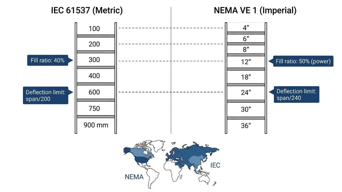
Perforated cable tray sizes are specified in either metric (mm) or imperial (inches) depending on the governing standard and project location — and mixing the two is one of the most common procurement errors in cross-border projects.
Metric sizing governs projects under IEC 61537, which is the primary cable tray standard across Europe, the Middle East, Southeast Asia, and most of Asia-Pacific. Under this system, tray widths run in increments of 50 mm or 100 mm — common widths are 100 mm, 150 mm, 200 mm, 300 mm, 400 mm, 600 mm, and 900 mm. Depths follow a similar logic: 35 mm, 50 mm, 60 mm, 75 mm, and 100 mm cover the majority of installations.
Imperial sizing applies to projects governed by NEMA VE 1, the standard published by the National Electrical Manufacturers Association for cable tray systems in North America. Here, widths are expressed in inches — 4 in, 6 in, 9 in, 12 in, 18 in, 24 in, and 36 in — with depths of 2 in, 3 in, 4 in, and 6 in being standard catalog offerings.
The nominal values look close enough to cause confusion. A 300 mm tray is approximately 11.8 in, not 12 in — that 5 mm gap affects fitting compatibility when mixing components from different supply chains. In a 2024 petrochemical plant expansion in Malaysia, a procurement team sourced tray sections from a metric manufacturer and fittings from a North American catalog. The 12 in × 4 in fittings did not align with the 300 mm × 100 mm tray flanges, requiring custom adapter plates that added roughly 3 weeks to the installation schedule.
| Metric Width | Imperial Equivalent | NEMA Catalog Width |
|---|---|---|
| 150 mm | 5.9 in | 6 in |
| 300 mm | 11.8 in | 12 in |
| 450 mm | 17.7 in | 18 in |
| 600 mm | 23.6 in | 24 in |
When specifying perforated cable tray for international projects, confirm the governing standard in the project specification before issuing a purchase order. A single line in the spec — “per IEC 61537” or “per NEMA VE 1” — determines which dimensional series applies and prevents downstream compatibility issues. The full IEC 61537 standard is available directly from the IEC webstore.
[Expert Insight]
– Never assume a “300 mm” tray from two different manufacturers shares the same external flange width — internal dimensions are standardized, external profiles are not.
– On projects that span multiple countries, specify the governing standard explicitly in the bill of materials, not just the project specification. Procurement teams working from BOMs alone may default to local catalog dimensions.
– Fitting compatibility is the highest-risk point in mixed-standard projects; verify flange profiles before bulk ordering tray sections.
Perforated cable tray depth is the dimension most directly tied to cable fill capacity, yet it’s frequently underspecified during early design phases. Choosing the wrong depth forces costly rerouting or parallel tray runs — a problem encountered in a 2024 pharmaceutical plant expansion in Suzhou where undersized 50 mm deep trays had to be replaced mid-installation with 100 mm units after cable schedules were finalized, adding roughly 15% to the cable management budget.
Perforated trays are manufactured in discrete depth increments, typically 25 mm, 50 mm, 75 mm, and 100 mm. Some heavy-duty series extend to 150 mm for large-diameter power cables. The 50 mm depth handles most low-voltage control and instrumentation cable bundles, while 100 mm becomes necessary when cables exceed 25 mm individual outer diameter or when fill ratios approach the 40% threshold.
Fill ratio governs how much of the tray’s cross-sectional area cables may occupy. NEMA VE 1 and both set practical ceilings around 40–50% of usable cross-section to allow heat dissipation and future cable additions. For a 150 mm wide × 75 mm deep tray, usable cross-section is approximately 11,250 mm², meaning cables should not exceed roughly 4,500–5,600 mm² of bundled cross-section. Exceeding this threshold triggers ampacity derating per NEC 310.15 or equivalent national standards.
Increasing depth rather than width is often the right call when floor space or structural bay spacing constrains tray width. A 100 mm deep tray on a 300 mm wide run carries more cable than a 50 mm deep tray on a 450 mm wide run, while occupying a narrower corridor footprint. However, deeper trays increase the tray’s own dead weight — a 100 mm deep perforated steel tray at 600 mm width can weigh 8–12 kg/m before any cable load, which affects hanger spacing and support structure sizing under IEC 61537 load class calculations.
A practical rule used by most cable management engineers is to keep the width-to-depth ratio between 3:1 and 6:1. Going narrower than 3:1 limits cable layering. Going wider than 6:1 creates a tray that flexes laterally under asymmetric cable loads. Staying within this band keeps the perforated cable tray structurally predictable across standard support spans of 1.2 m to 3 m.
A 100 mm deep perforated tray in 1.5 mm galvanized steel typically carries 40–60 kg/m at a 3 m span, while the same width in 25 mm depth may only support 15–20 kg/m under equivalent conditions .
Selecting depth early — before cable schedules are locked — prevents the most common and expensive rework scenario in cable routing projects.
Choosing the correct perforated cable tray size comes down to three variables working together: cable fill, load capacity, and available installation space. Getting any one of them wrong means either a costly rework or a system that fails inspection.
NEMA VE 1 recommends a maximum fill ratio of 40% for power cables and up to 50% for control or signal cables in a perforated tray. In practice, if your cable bundle cross-section totals 120 cm², you need a tray with at least 300 cm² of usable interior area — which typically points to a 300 mm wide × 100 mm deep tray as a starting point.
During the 2024 commercial building fit-out in Guangzhou referenced earlier, the project team initially specified 200 mm wide trays throughout. Mid-installation, cable counts on three floors exceeded the 40% fill threshold. Upgrading to 300 mm wide trays on those runs added roughly 12% to material cost on the affected sections — a figure that would have been zero with an upfront fill calculation.
Tray depth directly affects load-bearing capacity. A 50 mm deep perforated tray typically handles 30–50 kg/m under standard span conditions, while a 100 mm deep tray of the same width can reach 75–100 kg/m — a meaningful difference when routing heavy power feeders.
IEC 61537 classifies cable tray systems by load class (Class A through D), with proof load testing conducted at 1.5× the rated working load. For most commercial and light industrial applications, a 300 mm × 75 mm perforated tray rated at Class B (75 kg/m) covers the majority of scenarios without over-engineering the support structure. For guidance on support spacing and hanger selection that aligns with these load classes, the cable tray support spacing guide provides span tables for common tray profiles.
A common rule among experienced electrical contractors: size for current load, then add one width increment for future cables. If your calculation lands on a 200 mm wide tray, specify 300 mm. The incremental cost at installation is small; the cost of adding a parallel tray run later is not.
Width increments in perforated cable tray systems typically follow a standard progression — 100 mm, 150 mm, 200 mm, 300 mm, 400 mm, 500 mm, 600 mm — so moving up one step is straightforward and keeps the system within a consistent product family. Pairing the right tray size with compatible cable tray fittings — elbows, reducers, and tees — ensures the full run maintains dimensional consistency from section to section.
Once width, depth, and load class are confirmed, the remaining procurement decisions follow quickly. Material selection — hot-dip galvanized steel for outdoor or corrosive environments, pre-galvanized for indoor dry locations, stainless steel for food processing or chemical plants — is driven by the installation environment rather than size. Section length is almost always fixed at 2.4 m or 3 m per section across major manufacturers, so the size decisions made earlier determine fitting quantities and support hanger spacing directly.
For projects spanning multiple zones or floors, standardizing on two or three tray widths across the entire installation — rather than specifying the exact-fit width for each individual run — reduces procurement complexity without meaningfully increasing material cost. The cable tray installation guide covers how to translate a finalized size schedule into a complete bill of materials, including fitting allowances and support hardware quantities.
If the project involves a mix of power distribution and structured cabling on separate tray systems, consider whether a ladder cable tray is more appropriate for the heavy power runs — ladder trays offer higher load capacity per unit weight and better long-span performance, while perforated trays remain the better choice for signal and data cables that need continuous bottom support.
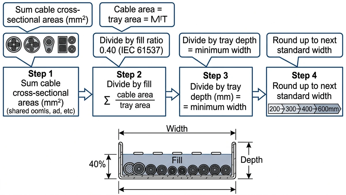
Add up the cross-sectional areas of all cables in the run, then select a tray width where that total represents no more than 40% of the tray’s usable cross-section — IEC 61537 sets this as the recommended fill ceiling for power cables in perforated trays. For example, a cable bundle totaling 6,000 mm² requires a tray with at least 15,000 mm² of usable cross-section, which typically corresponds to a 300 mm wide × 50 mm deep tray.
Perforated cable trays are generally manufactured in depths of 25 mm, 50 mm, 75 mm, and 100 mm, with some heavy-duty series reaching 150 mm for large-diameter power cables. The 50 mm depth covers most low-voltage control and instrumentation applications, while 100 mm is typically needed when individual cable outer diameters exceed 25 mm or when fill ratios approach the 40% threshold.
Metric sizing follows IEC 61537 and is standard across Europe, the Middle East, and Asia-Pacific, with widths in 50 mm or 100 mm increments. Imperial sizing follows NEMA VE 1 and applies to North American projects, with widths in inches (6 in, 12 in, 18 in, 24 in). A 300 mm metric tray measures approximately 11.8 in — close to 12 in but not interchangeable with NEMA fittings without verification.
Deeper trays have greater bending stiffness, which increases the load they can carry across a given span. A 100 mm deep perforated steel tray in 1.5 mm galvanized steel typically carries roughly 40–60 kg/m at a 3 m span, while a 25 mm deep tray of the same width may support only 15–20 kg/m under equivalent conditions. IEC 61537 load class ratings (Class A through D) formalize these differences through standardized proof load testing.
Sizing for current load plus one width increment is a widely used approach among electrical contractors — the incremental material cost at installation is minor compared to the cost of adding a parallel tray run after the ceiling is closed. If your fill calculation points to a 200 mm wide tray, specifying 300 mm is generally the more practical choice.
Perforated trays are generally preferred for signal cables, instrumentation wiring, and structured cabling runs where continuous bottom support prevents cable sag and the perforations provide adequate ventilation. Ladder trays tend to be the better choice for heavy power feeders over long spans, where their higher load-to-weight ratio and open design offer structural and thermal advantages.
A width-to-depth ratio between 3:1 and 6:1 is the range most tray manufacturers and selection guides recommend. Ratios narrower than 3:1 limit cable stacking, while ratios wider than 6:1 can cause lateral flexing under asymmetric cable loads. A 300 mm × 75 mm tray at 4:1 is a common general-purpose choice that balances fill capacity, structural stability, and support spacing across typical commercial spans.
