Address
304 North Cardinal St.
Dorchester Center, MA 02124
Work Hours
Monday to Friday: 7AM - 7PM
Weekend: 10AM - 5PM
Address
304 North Cardinal St.
Dorchester Center, MA 02124
Work Hours
Monday to Friday: 7AM - 7PM
Weekend: 10AM - 5PM
Get premium quality cable management systems directly from the manufacturer.
Fill out the form below to receive our catalog and pricing.
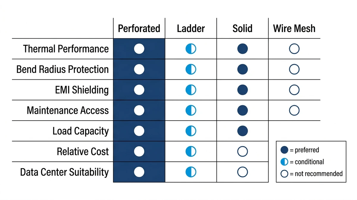
For data cable installations, the cable tray type directly determines airflow around cables, ease of future changes, and long-term signal integrity. Perforated cable trays win in most data environments because they balance ventilation, accessibility, and cost — but the right choice depends on load class, fill ratio, and environmental conditions.
A cable tray is a rigid cable management system that supports and routes cables along a fixed path — across ceilings, under raised floors, or along walls. Unlike conduit, trays allow open access at any point along the run, which matters in data environments where moves, adds, and changes happen frequently.
IEC 61537 governs cable tray and cable ladder systems, classifying them by load capacity from Class A (50 kg/m) up to Class D (200 kg/m). Data cable routing typically falls in the Class A to Class B (100 kg/m) range, since Cat6A and fiber optic cables are light compared to power cables.
Data cables are sensitive to two physical stressors that tray selection directly influences:
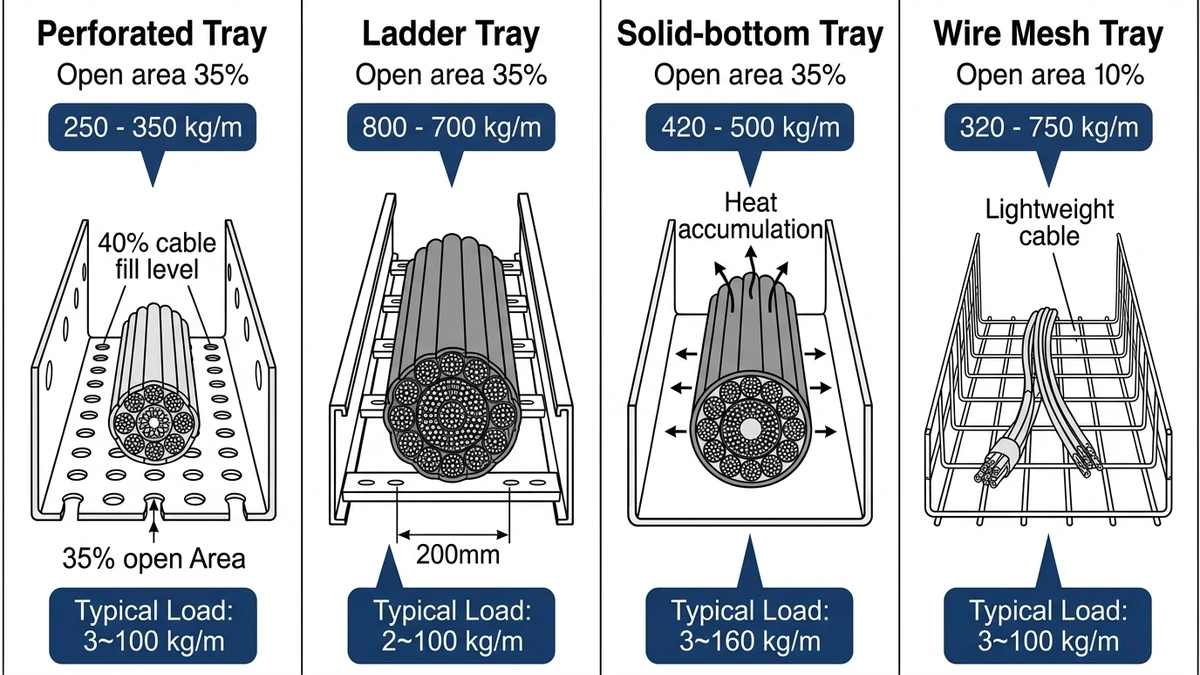
Four types appear most often in data cable routing:
Each type has a different structural profile, ventilation characteristic, and installation cost. The sections below compare them directly against the criteria that matter most for data cabling — ventilation, fill capacity, flexibility, and compliance with structured cabling standards.
[Expert Insight]
– IEC 61537 Class A (50 kg/m) covers the vast majority of structured data cabling installations; Class B (100 kg/m) becomes relevant when power and data cables share the same tray route.
– Tray width selection should account for a 40% initial fill ratio, leaving headroom for future cable additions without a full tray replacement.
– In raised-floor data centers, tray depth (sidewall height) matters as much as width — 50 mm sidewalls are generally sufficient for Cat6A bundles, while 100 mm sidewalls suit mixed data and low-voltage power runs.
– Corner fittings and radius bends are where bend-radius violations most often occur; specifying 90° horizontal bends with a minimum 300 mm inside radius eliminates most Cat6A signal degradation risks at direction changes.
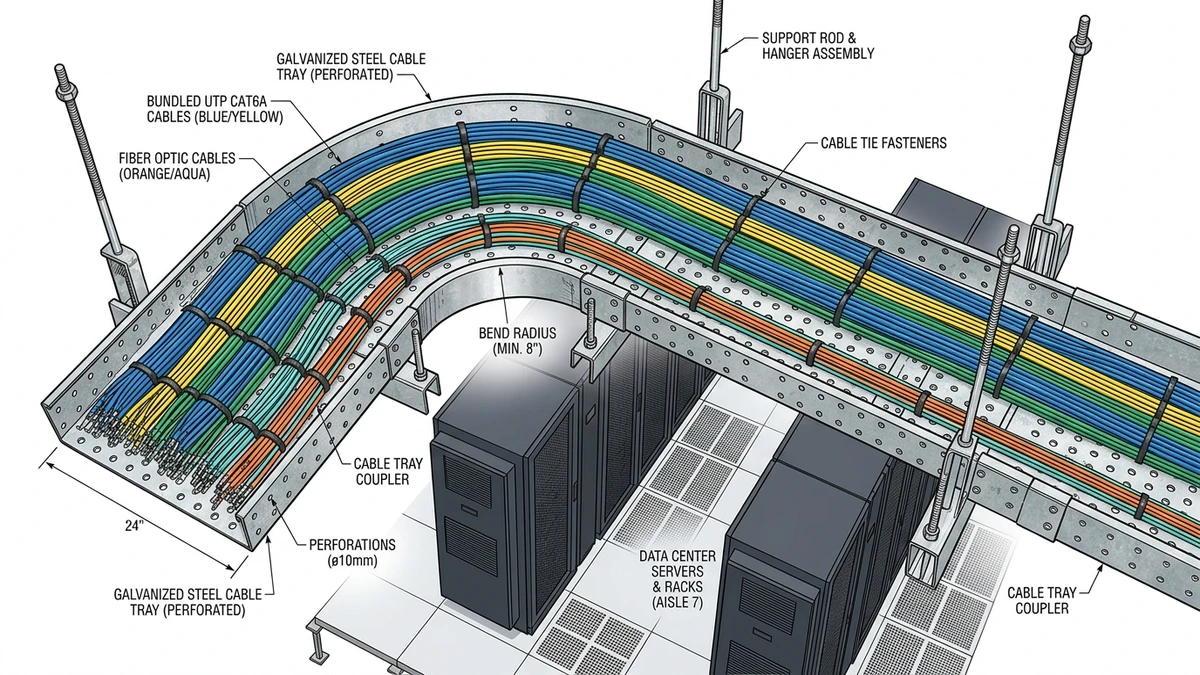
Perforated cable trays are the most widely specified option for data cables in structured cabling and data center environments — and the structural reason is straightforward. The tray base is stamped with a regular pattern of holes, typically 10 mm × 20 mm or 20 mm × 40 mm openings, covering 30–50% of the tray floor surface. This perforation pattern does two things simultaneously: it reduces dead weight while preserving the continuous bottom support that data cables require.
Unlike a cable ladder, which supports cables only at the rungs, a perforated tray provides a bearing surface across the full cable run. This matters for smaller-diameter data cables — Cat6A, OM4 fiber — that can deform or kink if unsupported over a span. The tray sidewalls, typically 50 mm or 100 mm high, contain the cable bundle laterally and prevent drift during cable pulls.
Under IEC 61537, perforated trays are load-classified from Class A (50 kg/m) to Class C (100 kg/m), with deflection limits set at L/200 of the span. A 500 mm wide perforated tray spanning 1.5 m under a 60 kg/m cable load typically deflects 4–6 mm — well within Class B compliance.
Perforated trays are produced in hot-dip galvanized steel (typically 1.5 mm or 2.0 mm base metal thickness), stainless steel for corrosive environments, and powder-coated mild steel for indoor structured cabling. Finish choice affects both corrosion resistance and load class retention over a 25-year service life. For most data center applications, hot-dip galvanized is the default; stainless becomes relevant in pharmaceutical manufacturing, coastal facilities, or anywhere chemical exposure is a documented risk.
Selecting the right perforated cable tray for a project means matching perforation ratio, material gauge, and finish to the actual environmental and load conditions — not just defaulting to the lightest available product.
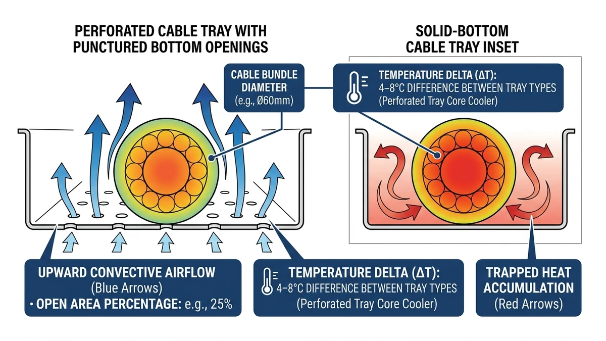
For data cable routing, thermal management is often the deciding factor. Perforated cable trays outperform solid-bottom alternatives because their open surface area allows passive airflow across the cable bundle. In a 2023 hyperscale data center fit-out in Shenzhen (approximately 8,000 m² of raised-floor space), switching from solid-bottom trays to perforated trays reduced average cable bundle temperatures by 6–9°C without any change to HVAC load.
A perforated tray with 30–40% open area allows convective airflow both through the tray floor and along the cable sides. Cat6A and fiber optic cables generate resistive heat during sustained high-bandwidth transmission. When cables are stacked in a solid tray, heat accumulates at the bundle core — the innermost cables can run 12–15°C hotter than the outermost layer under full load. Perforated trays break this thermal gradient by allowing cross-ventilation, keeping the entire bundle closer to ambient temperature.
Data cables don’t have the same flexibility as power cables when heat becomes a problem. Power cable engineers compensate by upsizing conductors using ampacity derating tables. For Cat6A or higher-category data cables, there’s no equivalent workaround — sustained heat exposure degrades signal integrity directly, and the only fix is keeping temperatures within the manufacturer’s rated range (typically ≤ 60°C for PVC-jacketed assemblies).
IEC 60364-5-52 governs current-carrying capacity and derating factors for grouped cables in cable management systems. When cables are grouped in a solid tray without ventilation, derating factors can reduce allowable current by 20–35% depending on group size and ambient temperature. Perforated trays, by maintaining airflow, allow engineers to apply less aggressive derating — typically 10–15% for groups of 6–9 cables — which directly affects cable sizing and overall material cost.
Fill ratio interacts with thermal performance in a non-linear way. A fill ratio above 50% in a solid tray creates a near-adiabatic core; the same fill ratio in a perforated tray remains thermally manageable because heat has an escape path through the floor perforations. That said, thermal benefit from perforations diminishes as fill ratio climbs above 40% of tray cross-section — at that density, cables begin blocking the perforation openings from below, reducing effective airflow by an estimated 50–70%. Cable management planning should target a fill ratio of 30–35% in perforated trays serving high-density data runs.
Not all perforated trays perform equally. Slot-pattern perforations oriented perpendicular to the cable run direction improve airflow distribution compared to round-hole patterns of the same open area percentage. IEC 61537 governs cable tray mechanical performance but does not specify thermal requirements directly — thermal derating for power cables is addressed under IEC 60364-5-52. For data cabling, ANSI/TIA-568 installation guidelines recommend maintaining cable bundle temperatures below the cable’s rated operating threshold, which perforated trays support passively without additional cooling infrastructure.
Trays with ≥ 35% perforation ratio provide sufficient airflow for most structured cabling applications. Below 25%, the thermal benefit diminishes significantly and approaches solid-bottom performance. Most established manufacturers target 35–45% open area as the practical optimum — enough airflow without compromising the structural load rating.
| Tray Type | Airflow Through Floor | Typical Bundle Temp Rise | Dust Accumulation Risk |
|---|---|---|---|
| Perforated | Yes (30–50% open area) | Low (6–9°C above ambient) | Moderate |
| Solid-bottom | No | High (15–20°C above ambient) | Low |
| Wire mesh | Yes (high open area) | Very low | High |
Wire mesh trays offer the best passive cooling but accumulate dust faster in environments without positive air pressure — and dust accumulation itself becomes a thermal insulation problem over time. Perforated trays strike a practical balance: enough open area for heat dissipation, enough floor coverage to limit particulate ingress.
Solid-bottom trays remain appropriate where physical cable protection is the priority — areas with chemical exposure, falling debris risk, or where electromagnetic shielding is required. In standard data center and office IT infrastructure environments, the thermal advantage of perforated trays is consistent and measurable.
[Expert Insight]
– Fill ratio above 40% in a solid-bottom tray typically triggers ampacity derating under IEC 60364-5-52; the same fill ratio in a perforated tray generally does not, which can eliminate the need to upsize cable cross-sections.
– In raised-floor plenums with limited ambient airflow, the difference between 30% and 45% perforation open area can mean the difference between staying within and exceeding the cable manufacturer’s 60°C continuous operating limit.
– Wire mesh trays are worth considering in server rooms with positive-pressure cooling, where dust ingress is controlled — the higher open area provides measurably better passive cooling than perforated trays at equivalent fill ratios.
– Perforations reduce tray structural rigidity by roughly 10–15% compared to solid-bottom trays of the same gauge; for pure data cable applications where cable weights stay under 15 kg/m, this trade-off is negligible.
The choice between perforated and solid-bottom trays comes down to three variables: thermal environment, cable protection requirements, and long-term flexibility. Here’s how they compare across the criteria that matter most in data cable routing.
Perforated trays win here, and the margin is significant in high-density installations. The 6–9°C temperature reduction documented in the Shenzhen hyperscale project translated directly into avoided derating — the project team avoided approximately 120 m of additional tray runs that would have been required to reduce bundle density in solid-bottom sections to achieve equivalent thermal performance.
Solid-bottom trays trap heat. In a ceiling void or raised-floor plenum with limited ambient airflow, that trapped heat accumulates over time and shortens cable service life. For a cable plant expected to run continuously for 15–20 years, that’s a meaningful lifecycle cost difference.
Solid-bottom trays provide better protection against falling debris, liquid splash, and physical impact. In manufacturing environments, food processing facilities, or anywhere cables run through areas with overhead activity, the enclosed base is a genuine advantage. Perforated trays offer partial protection — the floor openings are small enough to block most debris but won’t stop fine particulates or liquid ingress.
For data center environments with controlled access and clean-room conditions, this distinction rarely matters. For industrial or mixed-use facilities, it can be the deciding factor.
Both tray types support the same range of cable tray fittings — horizontal bends, tees, reducers, and risers. The difference shows up during cable additions. In a perforated tray, technicians can visually inspect fill levels through the floor openings and route new cables without disturbing existing bundles. In a solid-bottom tray, the only visibility is from above, which makes fill assessment harder and increases the risk of exceeding fill ratio limits unintentionally.
This matters in enterprise environments where the cable plant evolves continuously. A perforated tray installed at 35% fill leaves visible headroom; a solid-bottom tray at the same fill looks identical to one at 60% fill from above.
Solid-bottom trays carry higher loads at equivalent material gauge — typically 10–15% more than a perforated tray of the same width and steel thickness. For pure data cable applications where cable weights stay under 15 kg/m, this difference is negligible. Where heavier armored cables or mixed power-and-data runs share the route, engineers should verify the load class against IEC 61537 Class B or Class C requirements before specifying perforated over solid.
Understanding cable tray dimensions — width, depth, and span — is the starting point for any load class verification. A 300 mm wide perforated tray at 30% open area generally carries 40–60 kg/m under IEC 61537 Class B conditions; a solid tray of the same width rates at 60–80 kg/m.
Perforated trays are the standard choice for horizontal cable runs in data centers — above raised floors, in overhead cable management zones, and in inter-rack routing. The thermal advantage is consistent, the fill ratio is easy to monitor, and the open structure simplifies the frequent cable changes that data center environments demand.
For vertical cable runs in cable management systems between floors, ladder cable trays are often preferred for heavier fiber trunk cables, where the rung spacing provides adequate support and the open structure maximizes airflow on vertical runs.
In above-ceiling structured cabling installations, perforated trays handle the combination of Cat6A horizontal runs and fiber backbone cables without requiring separate tray routes for each cable type. The 50 mm sidewall depth suits most horizontal distribution runs; 100 mm depth is appropriate where cable counts are high or where future expansion is planned.
For a detailed walkthrough of sizing and support spacing, the cable tray installation guide covers span calculations, support bracket selection, and fill ratio management for structured cabling applications.
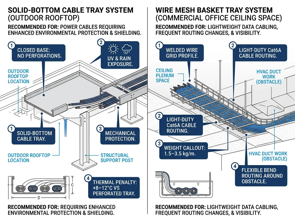
Solid-bottom trays are the better choice where cables run through areas with chemical exposure, falling debris, or physical impact risk. The enclosed base protects cable jackets from abrasion and contamination. Where thermal management is also a concern in these environments, engineers sometimes specify perforated trays with a solid cover — gaining the ventilation benefit of the perforated floor while protecting cables from above.
When power cables and data cables share a tray route, IEC 61537 and most structured cabling standards recommend physical separation — either separate tray sections or a divider within a wide tray. In these configurations, perforated trays provide thermal relief for both cable types, and the open structure makes it easier to maintain the required separation during future cable additions.
For projects where both cable types share infrastructure, reviewing cable tray systems that support divider accessories and mixed-use configurations is worth doing early in the design phase — retrofitting separation after installation is significantly more expensive.
Industry practice generally targets 30–35% fill ratio for perforated trays in high-density data environments, leaving enough open perforation area for passive airflow to function effectively. Exceeding 40% fill in a perforated tray begins to block floor openings from below, reducing the thermal benefit that makes perforated trays preferable to solid-bottom alternatives.
Higher perforation ratios improve airflow but reduce the cross-sectional material available to carry load. A 300 mm wide perforated tray at 30% open area typically carries 40–60 kg/m under IEC 61537 Class B conditions, compared to 60–80 kg/m for a solid-bottom tray of the same width and gauge — roughly a 10–15% capacity reduction depending on perforation pattern and steel thickness.
Perforated trays are available in hot-dip galvanized steel, stainless steel, and powder-coated mild steel. For outdoor installations or environments with chemical exposure, hot-dip galvanized or stainless steel versions are generally appropriate, with stainless steel preferred in coastal, pharmaceutical, or high-humidity industrial settings where long-term corrosion resistance is a design requirement.
Solid-bottom trays are generally the better choice where physical cable protection is the priority — areas with falling debris, liquid splash, chemical exposure, or where electromagnetic shielding of cable runs is required. In clean, controlled data center environments, the thermal disadvantage of solid-bottom trays typically outweighs their protection benefit for data cable applications.
IEC 61537 governs load classification and deflection limits for cable tray systems but does not prescribe specific perforation geometry or minimum open area percentages for thermal performance. Thermal derating for power cables is addressed under IEC 60364-5-52, while data cable temperature limits are governed by manufacturer specifications and ANSI/TIA-568 installation guidelines.
Wire mesh trays provide better passive cooling than perforated trays at equivalent fill ratios because their open area is significantly higher. The trade-off is faster dust accumulation in environments without positive air pressure, which can itself act as thermal insulation over time. Perforated trays offer a more practical balance for most data center environments where dust control is not guaranteed.
Support spacing for perforated cable trays is governed by the tray’s load class and the actual cable fill weight. For data cable applications where fill weights stay under 15 kg/m, support spans of 1.5 m are common for standard 1.5 mm gauge trays, with deflection checked against the IEC 61537 limit of L/200 of the span. Heavier fills or wider trays may require closer support spacing, which should be confirmed against the manufacturer’s published load tables.
