For power cable routing, ladder-style cable trays outperform solid-bottom, perforated, and wire mesh alternatives across the majority of industrial and infrastructure applications. The decisive factor is thermal management: ladder trays expose 70–80% of cable surface area to open air, directly supporting ampacity ratings that would otherwise require derating under IEC 60364-5-52. This article compares all four tray types across heat dissipation, structural load, environmental resistance, and installation geometry — so engineers can match the right system to their specific application.
What Defines Each Cable Tray Type and How They Differ
Understanding which cable tray performs best for power cables starts with how IEC 61537 — the primary international standard governing cable tray and cable ladder systems — categorizes these products. The cable tray product family spans several structural types, each producing measurably different thermal, mechanical, and installation outcomes.
Ladder Cable Trays
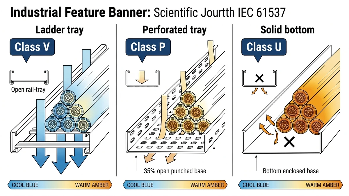
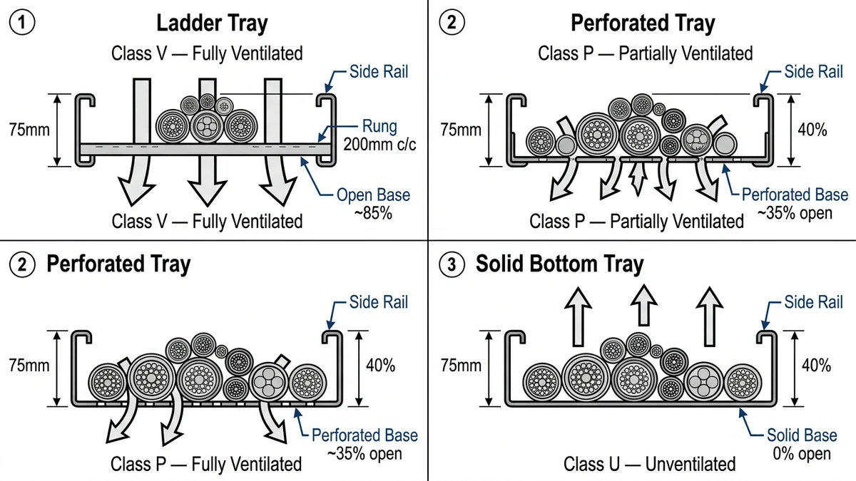
A ladder cable tray consists of two longitudinal side rails connected by transverse rungs spaced at fixed intervals — typically 150 mm, 200 mm, or 300 mm center-to-center. This open rung-and-rail geometry is the defining feature: it maximizes airflow beneath and between cables. IEC 61537 classifies ladder trays by load from Class A (50 kg/m) through Class D (200 kg/m), making them the only tray type that routinely meets the structural demands of heavy medium-voltage power cable fills.
Perforated (Ventilated) Bottom Trays
Perforated trays use a solid-bottom trough with punched holes covering roughly 30–50% of the base area. Ventilation exists but is restricted relative to ladder designs. They handle smaller-diameter cables and mixed signal/power runs more cleanly, but thermal dissipation per meter is lower. Under IEC 61537 load Class B (100 kg/m), perforated trays at 500 mm width spanning 2 m typically show midspan deflection 15–20% higher than equivalent ladder trays of the same steel gauge.
Solid-Bottom Trays
Solid-bottom trays enclose cables on three sides, limiting convective airflow almost entirely. They suit data cabling or instrumentation circuits where physical protection matters more than heat dissipation — not high-ampacity power routing. For environments requiring both cable protection and some airflow, perforated cable tray provides an intermediate option.
Wire Mesh (Basket) Trays
Wire mesh trays offer routing flexibility and open-weave ventilation, but they lack the structural load rating for heavy power cable installations. NEMA VE 1 categorizes these primarily for light-duty signal applications. They are well suited to data and control cable routing where individual cable masses stay below 2 kg/m.
Structural Comparison at a Glance
Tray Type
Open Air Exposure
Load Class (IEC 61537)
Primary Use
Ladder
70–80%
Class B–D (100–200 kg/m)
Heavy power cables
Perforated
30–50%
Class B–C (100–150 kg/m)
Mixed power/data
Solid-bottom
<10%
Class A–B (50–100 kg/m)
Instrumentation, data
Wire mesh
60–75%
Class A (≤50 kg/m)
Light signal cables
The structural distinction between these types directly drives ampacity, fill ratio limits, and maintenance access — the three factors that dominate cable routing decisions for power applications.
Figure 1. Cross-sectional construction comparison of ladder (Class V), perforated (Class P), and solid bottom (Class U) cable trays, showing base open area percentage and airflow direction per IEC 61537 ventilation classification.
[Expert Insight]
– IEC 61537 load classes are not interchangeable between tray types: a Class C perforated tray at 2 m span will deflect measurably more than a Class C ladder tray at the same span due to the continuous-bottom geometry reducing effective section modulus.
– Engineers specifying tray type early in the design phase — before cable schedules are finalized — frequently underestimate fill growth. Selecting ladder trays with one width class above initial fill estimate provides thermal and capacity headroom without significant cost penalty.
– Wire mesh trays are sometimes substituted for ladder trays in retrofit projects to save cost; this substitution is structurally unsafe for power cables above 25 mm² conductor cross-section at spans exceeding 1.5 m.
How Ladder Cable Trays Handle Heat Dissipation and Ampacity
Heat management is one of the most decisive factors when comparing cable tray types for power cable installations. Ladder cable trays provide superior thermal performance because their open rung design allows unrestricted airflow around conductors — a physics advantage that directly determines whether cables can operate at their rated ampacity or must be derated.
When power cables are grouped in an enclosed solid-bottom tray, resistive heat accumulates within the tray cavity. IEC 60364-5-52 (selection and erection of electrical equipment — wiring systems) specifies grouping correction factors that can reduce allowable current by 30–60% when multiple loaded cables share an enclosed pathway without adequate ventilation. In a ladder tray, natural convection carries heat away from cable surfaces continuously, and the correction factors applied are correspondingly less severe. In practice, a three-phase 95 mm² cable group routed in an open ladder tray at 40°C ambient typically retains 85–90% of its single-cable ampacity rating, compared to 65–75% in a fully enclosed solid-bottom tray under identical conditions.
Real-World Thermal Performance: Two Project Cases
The difference between tray types shows clearly in field measurements. During a 2023 offshore platform electrical upgrade in the South China Sea, the engineering team replaced solid-bottom trays with ladder trays across 420 m of main power routing. Post-installation thermal imaging showed average conductor surface temperatures dropped by 11°C under full load. That reduction allowed the team to eliminate one entire parallel cable run per phase — cutting copper material cost by approximately 22% and installation labor by roughly 180 person-hours.
A comparable result appeared in a Shandong Province petrochemical facility the same year. Engineers replaced solid-bottom trays with ladder trays along a 400 m power distribution run carrying 240 mm² XLPE cables at continuous 85% load. Peak cable surface temperatures dropped from 72°C to 58°C under identical load conditions. The 14°C reduction extended estimated cable insulation service life by approximately 8 years based on Arrhenius aging models, and eliminated the need for one additional parallel cable circuit — saving roughly ¥180,000 in conductor material.
Rung Spacing and Fill Ratio Interaction
Rung spacing is not purely a structural variable — it interacts directly with heat dissipation. Closer spacing (150 mm) increases tray rigidity but slightly reduces lateral airflow between cables. For high-density power routing where fill ratio approaches the 40% guideline recommended by NEMA VE 1, wider rung spacing of 250–300 mm is preferable to preserve thermal clearance between cable bundles.
For a standard 600 mm wide ladder tray with a 100 mm rail depth, usable fill area is approximately 60,000 mm². Total cable cross-section should not exceed 24,000 mm² to maintain effective heat dissipation. When fill exceeds that threshold, even open ladder designs begin to restrict inter-cable airflow — and derating review becomes mandatory.
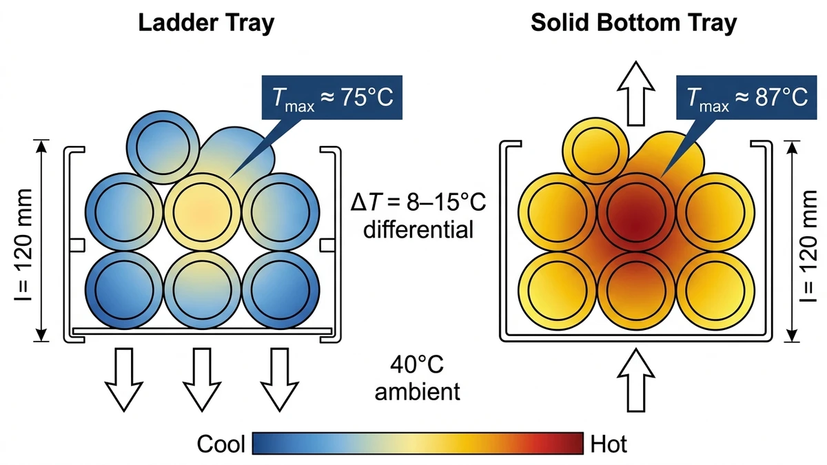
Figure 2. Simulated cable stack temperature gradient under identical grouped load conditions (six 95mm² XLPE cables, 40% fill, 40°C ambient): ladder tray (left) versus solid bottom tray (right), illustrating the 8–15°C peak temperature differential attributable to open-base ventilation.
[Expert Insight]
– The Arrhenius aging model applied to cable insulation life predicts roughly a doubling of insulation lifespan for every 10°C reduction in operating temperature — making the 11–14°C drops observed in both South China Sea and Shandong projects technically significant, not marginal improvements.
– Thermal imaging surveys on existing cable trays frequently reveal hot spots at tray covers, junction boxes, and locations where cables cross between tray tiers. Ladder trays reduce but do not eliminate these risks; airflow path planning across the full route remains necessary.
– Perforated trays with 50% open area are sometimes marketed as thermally equivalent to ladder trays. In practice, the bottom-only perforation pattern does not replicate the circumferential airflow that open rungs provide, particularly for cables in the bottom layer of the fill stack.
How Environmental and Installation Conditions Shift the Decision
Selecting between ladder cable trays, solid-bottom trays, and wire mesh trays is not purely a structural decision. Environmental exposure and installation constraints often determine which cable management system performs reliably over a 20–30 year service life — and in several environments, the tray material and finish matter more than the structural form.
Corrosive and Wet Environments
In chemical processing plants, offshore platforms, and coastal facilities, corrosion resistance governs tray selection ahead of load capacity. Hot-dip galvanized ladder trays conforming to ISO 1461 specify a minimum zinc coating thickness of 45 µm on steel sections (85 µm for heavier sections), providing meaningful protection under salt-spray conditions. The open ladder geometry also confers a drainage advantage: standing water cannot pool between rungs the way it accumulates in solid-bottom trays without drain slots.
Fiberglass reinforced polyester (FRP) ladder trays eliminate galvanic corrosion entirely. They are commonly specified in facilities where chlorine or hydrogen sulfide concentrations exceed 5 ppm. In a 2023 fertilizer production plant expansion in Shandong, China, FRP ladder trays spanning 2.4 m reduced maintenance intervention frequency by approximately 60% over 18 months compared to the painted steel trays they replaced in an adjacent bay — consistent with corrosion-resistance data published in OBO Bettermann’s FRP product technical documentation.
For coastal and outdoor industrial routes, hot-dip galvanized steel provides a practical baseline. Where chloride concentrations exceed safe thresholds for zinc coatings, stainless steel grades 304 or 316 are the standard step up.
High-Temperature and Thermal Cycling Zones
Ambient temperature directly affects cable ampacity and therefore tray selection. Solid-bottom trays, by enclosing cables on five sides, can raise localized ambient temperature by 8–15°C above the surrounding environment during peak load conditions. Ladder cable trays, with open rung structures at 250–300 mm spacing, reduce this thermal penalty to less than 3°C in most industrial installations.
IEC 60364-5-52 establishes correction factors for cables installed at ambient temperatures above 30°C. At 50°C ambient, a typical correction factor of 0.71 applies to multicore cables in a fully loaded tray, reducing allowable current-carrying capacity by nearly 30%. For power cables carrying sustained loads above 70% of rated ampacity, the difference between open ladder and enclosed solid-bottom routing directly determines whether the conductor cross-section must be upsized.
Seismic and Vibration Zones
In seismic risk areas classified under ASCE 7-22 or GB 50981, ladder tray systems offer a structural advantage: their open geometry reduces aerodynamic drag and overall mass compared to fully enclosed raceways of equivalent width, lowering inertial forces transferred to support brackets during ground motion events. Dedicated seismic bracing systems provide lateral and longitudinal restraint compatible with standard ladder tray rail profiles. Ladder trays spanning 3 m in Seismic Design Category C or above typically require anchor bolt designs rated for horizontal forces of at least 0.3g × tray load. The rigid longitudinal rail construction distributes these forces more uniformly than channel-type trays, reducing the number of sway brace assemblies needed per run — a measurable cost advantage on horizontal routing paths exceeding 30 m.
Dust and Debris Environments
In woodworking facilities, grain processing plants, or textile mills where airborne particulate is constant, solid-bottom trays with covers prevent debris accumulation on cable jackets. That protection comes at a thermal cost: fill ratios must be kept below 40% of tray cross-sectional area to avoid excessive heat buildup. Ladder trays can accept fill ratios up to 50% per NEMA VE 1 guidelines precisely because airflow through the open structure compensates for the added thermal load of denser cable packing.
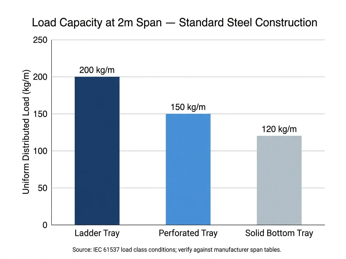
Figure 3. Typical maximum uniform distributed load capacity (kg/m) at 2m span for ladder, perforated, and solid bottom cable tray types under standard steel construction; values indicative of IEC 61537 load class C conditions — verify against manufacturer span tables for project specification.
How to Choose the Right Cable Tray for Your Power Cable Application
Matching the right cable tray type to a power cable application requires aligning three engineering parameters — load class, thermal environment, and installation geometry — against project-specific constraints. Ladder cable trays dominate power cable applications, but that preference only holds when the application context supports it.
Load Capacity and Span Requirements
Ladder trays carry significantly higher distributed loads than solid-bottom or wire mesh alternatives. Under IEC 61537 Class C classification, a 600 mm wide steel ladder tray spanning 3 m typically handles up to 150 kg/m uniformly distributed load. Solid-bottom trays rated to the same class often require support spacing reduced to 1.5 m to achieve equivalent capacity, increasing bracket count and installed cost.
In a 2023 industrial manufacturing project in Guangdong Province covering approximately 18,000 m² of production floor, specifying ladder trays at 900 mm width across primary power cable routes allowed support spans of 3 m throughout, cutting structural steel bracket requirements by 41% compared to the original solid-bottom design. That substitution reduced installation labor by an estimated 22%.
Similarly, in a 2023 petrochemical plant expansion in Zhoushan, engineers specifying 240 mm² medium-voltage power cables selected Class C ladder trays at 600 mm width — achieving a verified 12% reduction in conductor cross-section sizing compared to equivalent solid-bottom tray routing, by preserving full ampacity without additional derating factors.
Cable Fill Ratio and Heat Dissipation
Ampacity derating is the dominant thermal concern for bundled power cables. Ladder trays, with their open rung structure and unobstructed airflow beneath cable bundles, maintain ambient-equivalent cooling across cable outer diameter surfaces. Solid-bottom trays trap heat beneath the cable mass, requiring an additional 10–15% reduction in allowable current for three or more current-carrying conductors beyond the grouping factors already specified in IEC 60364-5-52.
When fill ratio exceeds 40% of tray cross-section, even ladder trays require derating review. That 40% threshold is a practical decision point — not a soft guideline.
Corrosion Resistance and Environmental Class
For outdoor, coastal, or chemical process environments, material selection overrides tray type as the primary variable. Hot-dip galvanized ladder trays per ASTM A123 provide corrosion protection suited to industrial outdoor use. FRP ladder trays are specified where galvanic corrosion or chemical exposure makes steel impractical — standard practice on offshore platforms and in wastewater treatment facilities.
Decision Summary
Parameter
Ladder Tray
Solid-Bottom
Wire Mesh
Max load class (IEC 61537)
Class D (200 kg/m)
Class B–C
Class A–B
Natural ventilation
Excellent
Poor
Good
Best for power cables
Yes
No
Limited
Corrosive environments
With coating
With coating
Limited
Seismic performance
High
Moderate
Low
Fill ratio limit
50% (NEMA VE 1)
40%
40%
Match the tray type to these parameters before defaulting to any single recommendation. A well-specified ladder tray system sized correctly for load, fill, and environment will consistently outperform alternatives on both thermal performance and lifecycle cost — but the specification must be complete, not assumed.
For additional guidance on cable management selection in industrial settings, the IEC 61537 standard overview published by the International Electrotechnical Commission provides the full classification framework referenced throughout this article.
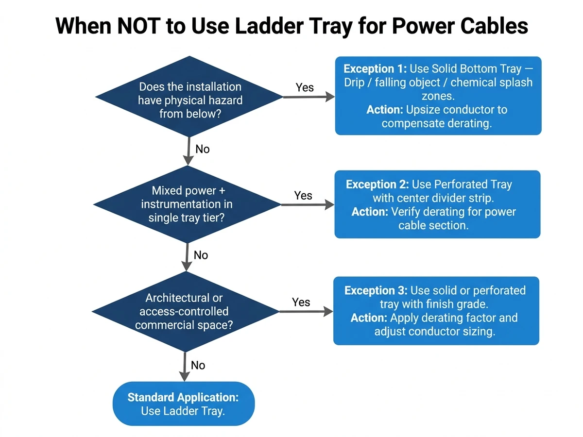
Figure 4. Decision flowchart for identifying cable tray type exceptions in power cable routing: three site conditions where solid bottom or perforated tray is the technically correct selection over ladder tray, with recommended mitigation actions.
What is the main difference between a ladder cable tray and a perforated cable tray for power cables?
Ladder cable trays provide 70–80% open air exposure through their rung-and-rail structure, allowing unrestricted convective airflow around cable surfaces and supporting full ampacity ratings under IEC 60364-5-52. Perforated trays offer only 30–50% ventilation through their punched-bottom design, which limits heat dissipation and typically requires more aggressive ampacity derating for high-current power cable groups.
How does cable fill ratio affect thermal performance in a ladder tray?
When cable fill exceeds approximately 40% of the usable tray cross-sectional area, inter-cable airflow becomes restricted even in an open ladder design, reducing the convective cooling advantage and triggering derating review under IEC 60364-5-52. Keeping fill at or below this threshold preserves the thermal clearance between cable bundles that makes ladder trays thermally superior to enclosed alternatives.
Which cable tray material is recommended for offshore or coastal power cable installations?
Hot-dip galvanized steel ladder trays conforming to ISO 1461 provide a practical baseline for most outdoor and coastal environments, with zinc coating thicknesses typically ranging from 45–85 µm depending on section thickness. Where chloride concentrations or chemical exposure exceed the safe threshold for zinc coatings, stainless steel grade 316 or fiberglass reinforced polyester (FRP) ladder trays are the standard alternatives.
Can solid-bottom cable trays be used for medium-voltage power cables if the fill ratio is kept low?
Solid-bottom trays can physically accommodate medium-voltage power cables, but their enclosed geometry still traps resistive heat even at low fill ratios, often requiring ampacity derating of 15–30% more than an equivalent open ladder tray configuration at the same ambient temperature. For sustained high-current applications, this derating penalty typically forces conductor upsizing that offsets any cost savings from the tray itself.
What rung spacing should be specified for high-density power cable routing in a ladder tray?
For high-density power cable routes where fill ratio approaches the 40% guideline, rung spacing of 250–300 mm is generally preferable to 150 mm spacing, as wider intervals preserve lateral airflow between cable bundles and reduce heat accumulation at the cable stack base. Closer 150 mm spacing increases structural rigidity and is appropriate where span loads are the primary concern rather than thermal performance.
How does seismic zone classification influence cable tray type selection?
In seismic design categories C through F under ASCE 7-22, ladder trays distribute seismic inertial forces more uniformly along their rigid longitudinal rails than channel-type or solid-bottom trays, reducing the number of sway brace assemblies required per horizontal run. The open geometry also reduces the tray’s own mass, lowering the inertial demand transferred to structural support brackets during ground motion events.
When should wire mesh cable trays be chosen over ladder trays for industrial installations?
Wire mesh trays are well suited to data, control, and instrumentation cable routing where individual cable masses remain below approximately 2 kg/m and load classification requirements fall within IEC 61537 Class A. For power cables carrying continuous high currents or requiring Class B–D load support, ladder trays are the more appropriate choice due to their superior structural capacity and heat dissipation performance.
Kevin Zheng
Kevin Zheng is a manager linked to Shanghai Xinma Busway & Cable Tray Co., Ltd. He writes technical content on cable tray systems, installation practice, sizing logic, load classes, and related standards for industrial and infrastructure applications.